 Log In
 Register Now!
 Help
Help

https://kephost.net/p/2022/13/3605_ea6d27203cf8.png
Hello.
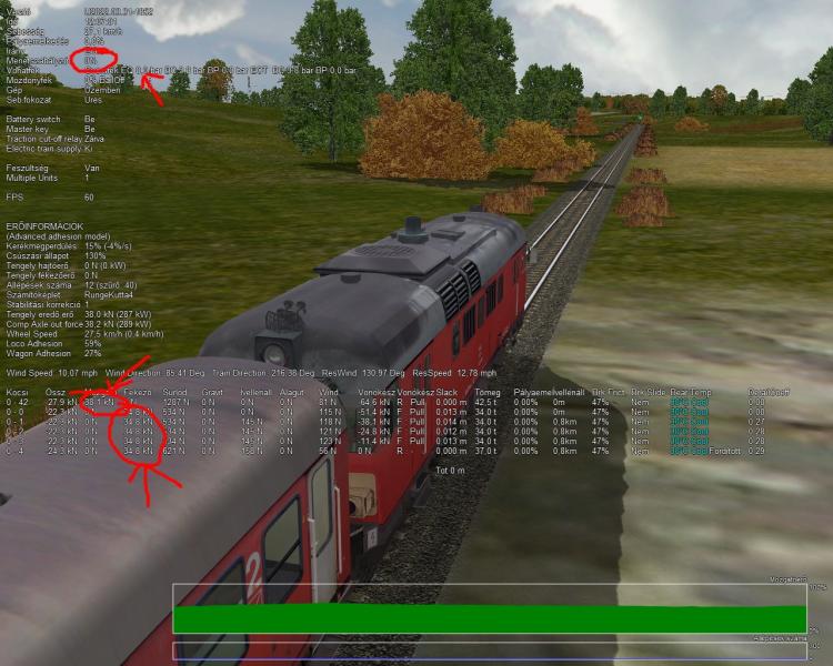
Unfortunately, it didn't get good. The force and torque are still 0.
The bottom row belongs to the control car, both have a value of 0 as they should be.
Regards Laci1959
Diesel Mechanical Locomotive
Rate Topic:
 1 Votes
#61

- Foreman Of Engines
-

- Group: Status: Contributing Member
- Posts: 949
- Joined: 01-March 15
- Gender:Male
- Simulator:Alföld
-
Country:

Posted 29 March 2022 - 08:11 AM
#62
- Open Rails Developer
-

- Group: Status: Elite Member
- Posts: 1,889
- Joined: 24-June 11
- Gender:Male
-
Country:

Posted 29 March 2022 - 07:20 PM
 Laci1959, on 29 March 2022 - 08:11 AM, said:
Unfortunately, it didn't get good. The force and torque are still 0.
The bottom row belongs to the control car, both have a value of 0 as they should be.
The bottom row belongs to the control car, both have a value of 0 as they should be.
You don't seem to have the latest Unstable version in which the patch was done.
Please update the Unstable version, and try it again.
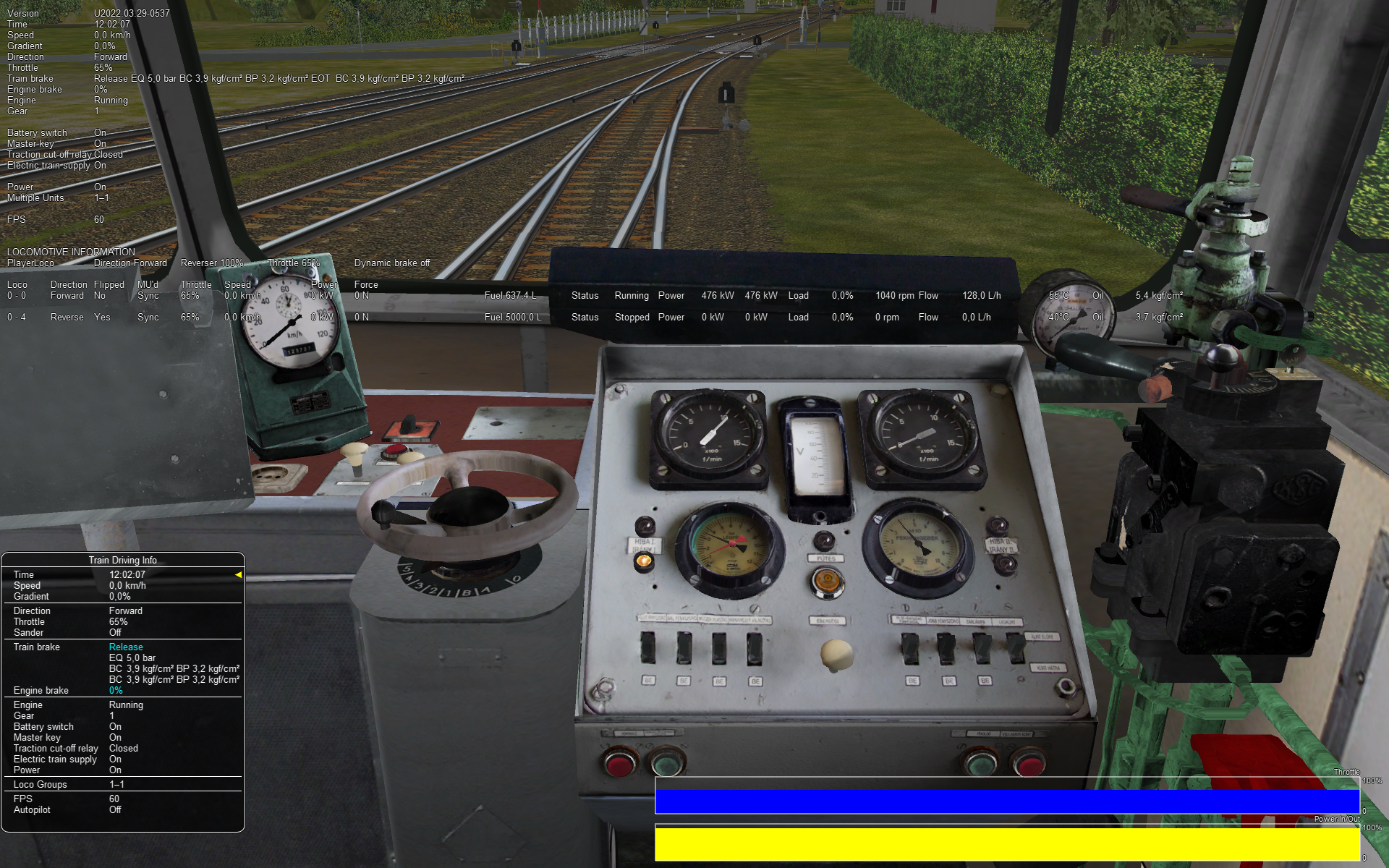
The screenshot below form the latest version shows that the force and power values are working.
Attached thumbnail(s)
#63
- Foreman Of Engines
-
- Group: Status: Contributing Member
- Posts: 949
- Joined: 01-March 15
- Gender:Male
- Simulator:Alföld
-
Country:
Posted 30 March 2022 - 12:09 PM
Hello.
When I read your request, I immediately updated the OR. Back then, even the version you saw in the picture was the latest. I’m sorry I didn’t keep an eye on my other activities.
I confirm it works with version 1807.
Sincerely, Laci 1959
When I read your request, I immediately updated the OR. Back then, even the version you saw in the picture was the latest. I’m sorry I didn’t keep an eye on my other activities.
I confirm it works with version 1807.
Sincerely, Laci 1959
#64
- Apprentice
-

- Group: Status: Dispatcher
- Posts: 34
- Joined: 20-February 14
- Gender:Male
- Simulator:OR
-
Country:
Posted 01 April 2022 - 02:24 AM
steamer_ctn, on 29 March 2022 - 07:20 PM, said:
You don't seem to have the latest Unstable version in which the patch was done.
Please update the Unstable version, and try it again.
The screenshot below form the latest version shows that the force and power values are working.
Please update the Unstable version, and try it again.
The screenshot below form the latest version shows that the force and power values are working.
Hello!
First of all, thank you for your work!
But something is still not good.
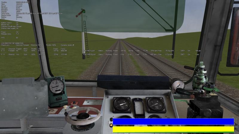
I am using version 1652 before the transmission code was modified. (Picture 1)
In the second picture, the latest unstable version is 1852.
There is no change in the eng.
Yet the driving dynamics are completely different just because of the version difference.
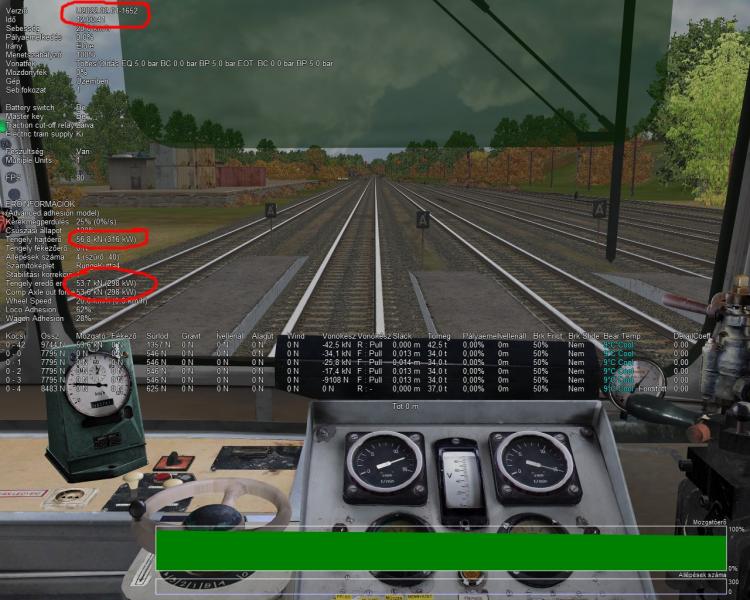
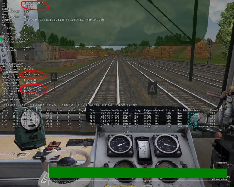
The third image shows that when braking, 0% of the drive still simulates a drive.
Motor vehicle with automatic transmission.
Latest unstable version (1852).
Works perfectly with the 1652!
Thanks in advance for the development!
#65
- Conductor
-

- Group: Status: Active Member
- Posts: 395
- Joined: 30-March 20
- Gender:Male
- Simulator:Open Rails
-
Country:

Posted 01 April 2022 - 05:01 AM
Hi,
This differences aren't caused by the recent development in diesel mechanical locomotives. The inaccurate results are caused by my recent changes to the adhesion model (which aren't finished yet).
I have corrected three or four errors in the advanced adhesion model, but there are some things to be fixed yet. Also, the "Motive Force" column is not really showing the tractive force, but the "axle out force".
The main issue is that the wheel moment of inertia has an extremely high default value, which must be lowered, using a sane default.
#66
- Foreman Of Engines
-
- Group: Status: Contributing Member
- Posts: 949
- Joined: 01-March 15
- Gender:Male
- Simulator:Alföld
-
Country:
Posted 01 April 2022 - 07:32 AM
https://kephost.net/p/2022/13/931_c4d983b878db.png
Hello.
Pictured is the MD traction wheel circumference traction speed torque curve. That is, the torque at the circumference of the wheel.
Such drawings are commonly used to create ORTSTractionCharacteristics or ORTSMaxTractiveForceCurves. It is clear that it is not specified for throttle positions, but only a curve. Each stage of the hydromechanical gear is connected by a thin vertical line. Unfortunately, neither ORTSTractionCharacteristics nor ORTSMaxTractiveForceCurves really support this type of representation.
I think setting up ORTSInertia would help if users could get real data, but that’s almost impossible. This is how the estimate stays.
Sincerely, Laci 1959
Hello.
Pictured is the MD traction wheel circumference traction speed torque curve. That is, the torque at the circumference of the wheel.
Such drawings are commonly used to create ORTSTractionCharacteristics or ORTSMaxTractiveForceCurves. It is clear that it is not specified for throttle positions, but only a curve. Each stage of the hydromechanical gear is connected by a thin vertical line. Unfortunately, neither ORTSTractionCharacteristics nor ORTSMaxTractiveForceCurves really support this type of representation.
Quote
The main issue is that the wheel moment of inertia has an extremely high default value, which must be lowered, using a sane default.
I think setting up ORTSInertia would help if users could get real data, but that’s almost impossible. This is how the estimate stays.
Sincerely, Laci 1959
#67
- Superintendant
-
- Group: Status: Elite Member
- Posts: 1,249
- Joined: 25-September 17
- Gender:Male
- Simulator:Open Rails
-
Country:

Posted 01 April 2022 - 10:52 AM
Laci1959, on 01 April 2022 - 07:32 AM, said:
Unfortunately, neither ORTSTractionCharacteristics nor ORTSMaxTractiveForceCurves really support this type of representation.
Sincerely, Laci 1959
Yes for some time I have been hoping for a good model of a hydro-mechanical transmission.
Hopefully the recent work on mechanical transmissions will help towards that.
A pure hydraulic transmission can easily be modelled with tractive force curves.
Thanks for your diagram. It is exactly what I wanted when I posted this:
http://www.elvastowe...post__p__275446
It is very much the same as the Voith transmission on some German locos like the V100. There are two fixed gear ratios that can be selected when the loco is stationary. (At the moment that is two different eng files.) The transmission itself clearly shows one torque converter followed by two direct (mechanical) drive stages.
#68
- Foreman Of Engines
-
- Group: Status: Contributing Member
- Posts: 949
- Joined: 01-March 15
- Gender:Male
- Simulator:Alföld
-
Country:
Posted 01 April 2022 - 11:35 AM
I just need a good characteristic curve for a good hydromechanical gearbox. If there is no visible sign that the transmission is working, perhaps it could work as a smooth diesel locomotive.
Maybe Peter will occasionally program a gearbox that can only be engaged in a stationary position without stopping the engine. We have locomotives like this. With line and reversing gear.
Anyway, I uploaded the picture to see if there will be an ORTSMaxGEARTractiveForceCurves that adjusts to the gear ratios. Perhaps that would be the best solution for mechanical locomotives. I don't know how feasible this is.
#69
- Apprentice
-
- Group: Status: Dispatcher
- Posts: 34
- Joined: 20-February 14
- Gender:Male
- Simulator:OR
-
Country:
Posted 01 April 2022 - 03:54 PM
cesarbl, on 01 April 2022 - 05:01 AM, said:
The main issue is that the wheel moment of inertia has an extremely high default value, which must be lowered, using a sane default.
Hi!
Thank you for the answer.
Can I do this with the ORTSInertia command?
I tried but saw no change. Maybe I put it in the wrong way.
Would you please give me an example of how I can use it? Thanks.
Quote
Unfortunately, neither ORTSTractionCharacteristics nor ORTSMaxTractiveForceCurves really support this type of representation.
You can do this with the ORTSTractionCharacteristics command in the current program.
I solved this for MD.
At the shift speed, I entered the speed with a decimal precision and assigned traction to it, and it works perfectly
#70
- Conductor
-
- Group: Status: Active Member
- Posts: 395
- Joined: 30-March 20
- Gender:Male
- Simulator:Open Rails
-
Country:
Posted 01 April 2022 - 10:09 PM
This is the full command. It is added to the wagon section of the .eng file.
Inertia is given in kg*m^2. Default is 30000, but my estimates say that for most diesel and electric engines it is around 1000.
Note that until slip control is implemented, wheelslip will be more severe with the lower inertia.
ORTSAdhesion ( WheelSet ( Axle( ORTSInertia( 1000 ) ) ) )
Inertia is given in kg*m^2. Default is 30000, but my estimates say that for most diesel and electric engines it is around 1000.
Note that until slip control is implemented, wheelslip will be more severe with the lower inertia.