Elvas Tower: Planning area of the ETCS DMI - Elvas Tower

Jump to content

Posting Rules

All new threads will be started by members of the Open Rails team, Staff, and/or Admins. Existing threads started in other forums may get moved here when it makes sense to do so.

Once a thread is started any member may post replies to it.
  • 15 Pages +
  • « First
  • 4
  • 5
  • 6
  • 7
  • 8
  • Last »
  • You cannot start a new topic
  • You cannot reply to this topic

Planning area of the ETCS DMI Rate Topic: ***** 2 Votes

#51 User is offline   cesarbl 

  • Conductor
  • Group: Status: Active Member
  • Posts: 395
  • Joined: 30-March 20
  • Gender:Male
  • Simulator:Open Rails
  • Country:

Posted 30 November 2020 - 02:27 AM

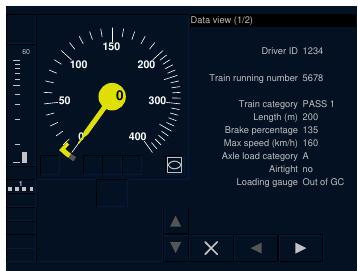
Re the needle color, according to the specs it should be yellow if train speed is above or equal to target speed, even if it is zero. I found an example in the specification:
Attached Image: yellowneedle.jpg

I'll change the way the gradient items are added so no exception is raised, thanks for investigating that.

#52 User is offline   Csantucci 

  • Member, Board of Directors
  • Group: Status: Elite Member
  • Posts: 7,015
  • Joined: 31-December 11
  • Gender:Male
  • Country:

Posted 30 November 2020 - 02:57 AM

Thanks, César.

#53 User is offline   Csantucci 

  • Member, Board of Directors
  • Group: Status: Elite Member
  • Posts: 7,015
  • Joined: 31-December 11
  • Gender:Male
  • Country:

Posted 30 November 2020 - 04:25 AM

Hi César,
I wanted to start with the indication distance and marker. I set the indication distance only and got a "System.InvalidOperationException: Nullable object must have a value." crash here at line 323 of PlanningWindow.cs
                bool im = (IndicationMarkerDistanceM??-1) > 0 && IndicationMarkerTarget.Value.Equals(cur);

So it seems that the target and distance must be defined together. Is this conceptually necessary?

By the way some day ago you also wrote about developing the braking bar and the text area. If numbers and strings would be visible (I increased a bit the size in the versions I have) I'm interest in using them: in my braking bar I couldn't implement the above square that increases its dimension, and also the text area I implementes is quite elementary (I display .ace files directly and not strings). What I'd need is that two parts should again be freely and separately selectable.

#54 User is offline   cesarbl 

  • Conductor
  • Group: Status: Active Member
  • Posts: 395
  • Joined: 30-March 20
  • Gender:Male
  • Simulator:Open Rails
  • Country:

Posted 30 November 2020 - 05:23 AM

The indication target (which is shown in yellow instead of grey) is the one which the driver must obey first, because it has the nearest indication supervision limit. The indication marker (the yellow horizontal line in the planning area) shows the distance to the point were the driver should start braking. At that point, the ETCS enters in Target Speed Monitoring, where no indication target exists, so all targets are shown in grey. Anyway, the code you are showing is pretty stupid and I will change it. If the script wants to display the indication marker without indication target or vice-versa, I wont stop it from doing it.

I'm making slow progress with the distance to target and the colored square. I'll try to find more time to finish it, and then I will start with the message area.
For the font size, I'll add a check such that if the DMI size is small, it will be increased a bit. I know what a pain is creating text messages with .ace files. A few years ago I created an ETCS script (not as accurate as the one I have now) and I had to do combinations of ALERTER_DISPLAY, ASPECT_DISPLAY and other controls to display messages, as no ORTS_TCS controls were available at that moment (thank you Carlo for adding them).

Edit: Use this line instead of the previous one
bool im = IndicationMarkerTarget.Equals(cur);


#55 User is offline   Csantucci 

  • Member, Board of Directors
  • Group: Status: Elite Member
  • Posts: 7,015
  • Joined: 31-December 11
  • Gender:Male
  • Country:

Posted 30 November 2020 - 06:00 AM

Thanks, that works so.
Re small chars, also the gradients in the planning area are hardly readable.

#56 User is offline   cesarbl 

  • Conductor
  • Group: Status: Active Member
  • Posts: 395
  • Joined: 30-March 20
  • Gender:Male
  • Simulator:Open Rails
  • Country:

Posted 30 November 2020 - 07:47 AM

I corrected the bugs pointed by Carlo and increased the font sizes a little bit (please tell me if it looks better than before). I added the target distance indicators (which can be controlled via the ETCSStatus.TargetDistanceM variable) and the square colored rectangles at the top left corner of the DMI. These squares are controlled by ETCSStatus.TimeToIndicationS. Positive values display a white rectangle centered on a grey rectangle; the lower the TTI value, the bigger the white rectangle is. Negative values display a rectangle with the same color as the needle; the closer to zero the bigger.

In order to keep compatibility with existing circular speed gauges I have made some translations and scales, so I'm afraid you'll have to reposition the DMI, Carlo.

Easy calculation of the time to indication for speed based curves:
For positive values, TTI = Math.Max((indicationcurveMpS - speedMpS)/accelerationMpS2, 0);
For negative values (time to permitted), TTI = -Math.Max((permittedcurveMpS - speedMpS)/accelerationMpS2, 0);

#57 User is offline   Csantucci 

  • Member, Board of Directors
  • Group: Status: Elite Member
  • Posts: 7,015
  • Joined: 31-December 11
  • Gender:Male
  • Country:

Posted 30 November 2020 - 12:06 PM

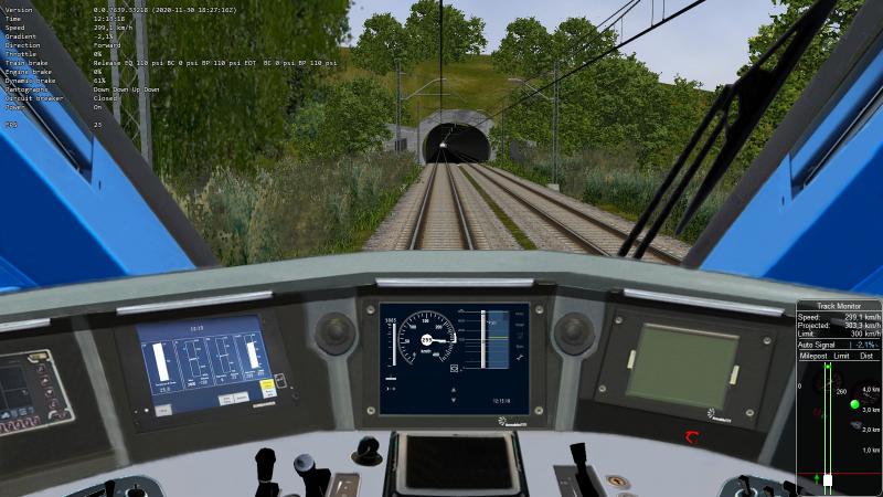
I merged the new ETCS commit, rescaled the DMI, and now in effect the characters have a quite better readability. Here a picture

Attached Image: BiggerChars.jpg

I had no more crashes.
I was also able to have a working Indication bar rolling down. I now understand how useful it is for a train driver.

The small segments above and below the speed markers still appear and disappear.

I will now try your new functionalities... I'm not able to keep your rithm. :)

#58 User is offline   Csantucci 

  • Member, Board of Directors
  • Group: Status: Elite Member
  • Posts: 7,015
  • Joined: 31-December 11
  • Gender:Male
  • Country:

Posted 30 November 2020 - 01:16 PM

César, I have some questions about your formulas above: Is accelerationMpS2 the istantaneous train acceleration, or is it the opposite of the max deceleration used in the speed curves?
When does the display of the squares start? At the beginning of TSM?
Due to the fact that the train is decelerating, in case accelerationMpS2 is the speed of the train, it should be negative, so TTI = 0 if indicationCurveMpS is > speedMpS. Is this correct?

#59 User is offline   cesarbl 

  • Conductor
  • Group: Status: Active Member
  • Posts: 395
  • Joined: 30-March 20
  • Gender:Male
  • Simulator:Open Rails
  • Country:

Posted 30 November 2020 - 01:37 PM

Sorry for not explaining that. The acceleration I used in the formulas is the decceleration as used in the SpeedCurve (as a positive value).
The grey time to indication is shown in CSM when indicationSpeedMpS>speedMpS, but only if there are bad adhesion conditions (slippery rail). If TTI>10, nothing is shown, if TTI decreases the square will increase.
The yellow square is shown only in target speed monitoring and I think it follows the same logic as the Time to Indication but with permitedSpeed instead of indicationSpeed. However, I haven't found a document where this is explained. I reused the TTI variable, but maybe it is adequate to create a Time To Permitted parameter to keep them separate. With the logic used now, if TTI<-10 no square will be shown, and if TTI reaches 0 the yellow square will become bigger.

Now that I think of it, I will define another variable for the yellow square, because using negative values seems confusing, and will provide wrong results if TTI=0.

I haven't tested the formulas, so if they don't fit well please tell me and I will find others.

#60 User is offline   Csantucci 

  • Member, Board of Directors
  • Group: Status: Elite Member
  • Posts: 7,015
  • Joined: 31-December 11
  • Gender:Male
  • Country:

Posted 01 December 2020 - 02:56 AM

Hi César,
I believe you have inverted the colours of the gradient profile. They should be white (or light grey) for positive gradients, and dark grey for negative gradients, while you display the opposite, as can be seen in the picture in my post above. Maybe you were misled by the fact that Locomotive.ElevationPercent is negative for positive gradients (!)

Re Time to indication I have found in Chapter 3 of the ETMS/ETCS SRS the following statement:
"3.13.10.3.10 If A_MAXREDADH (see 3.13.6.2.1.6) requests a time to Indication as
supplementary DMI information, the on-board equipment shall compute the Time to
Indication (TTI) as the time to travel at the estimated speed the remaining distance to
the first Indication location (as specified in 3.13.10.3.8 and 3.13.10.3.8.1). The onboard
equipment shall inform the driver as long as this time is shorter than a fixed
value (refer to A.3.1).
"

  • 15 Pages +
  • « First
  • 4
  • 5
  • 6
  • 7
  • 8
  • Last »
  • You cannot start a new topic
  • You cannot reply to this topic

2 User(s) are reading this topic
0 members, 2 guests, 0 anonymous users