Log In
 Register Now!
 Help
Help

The TCS of the HST where I'm working on operates both with the national TCS SCMT-RSC as well with the European one ETCS L2. Switching occurs automatically at TCS border points. I implemented such switching within the TCS script, and started implemented a very, very stripped down appearance of ETCS L2 DMI with the features available as of now.
However there is at least one display section of the DMI that can't be implemented satisfactorily with what is available today, and this is the Planning area (a sort of TrackMonitor).
Some years ago Peter (gpz) did a very good job, that I'm using, by generating a DriverMachineInterface.cs C# file, that is part of the OR solution, and that includes the management of the ETCS tachograph present in the ETCS DMI. Already seeing the name of the file, I expect that Peter was considering a possible extension of the file to further features of the ETCS DMI.
So the questions are:
1) is it correct to add to such file also the management of the Planning area of the DMI?
2) César has written here in the forum that he has done - as I interpret it - considerable work in implementing ETCS for OR. Could it be possible for him to pass to DriverMachineInterface.cs the part of code that implements the Planning area (and maybe parts of code that implement other parts of ETCS)?
3) if not, is someone (e.g. Peter) willing to work on such functionality? (I found a very old discussion about that here in the forum)
4) if not, as a pure hypothesis I might consider to try to develop something to be added to DriverMachineInterface.cs, but that's not the solution I prefer, as I'm sure the two people above would do the job much better than me.
Planning area of the ETCS DMI
Rate Topic:
 2 Votes
#1

- Member, Board of Directors
-

- Group: Posts: Elite Member
- Posts: 7,463
- Joined: 31-December 11
- Gender:Male
-
Country:

Posted 17 November 2020 - 08:37 AM
#2
- Engineer
-

- Group: Posts: Contributing Member
- Posts: 587
- Joined: 30-March 20
- Gender:Male
- Simulator:Open Rails
-
Country:

Posted 17 November 2020 - 08:58 AM
I have an ETCS with both DMI and EVC in an advanced stage of development. However, it is written in C++, as the DMI was intended to run in a standalone Raspberry Pi (or something similar). Many years ago I tried to use the standard OR scripting interface for the EVC, but as only one source file is allowed I started getting monster files, and I was too young to provide a solution for that. Porting everything to C# would require a lot of work, but rewriting the most important DMI parts is achievable. Having an in-cab ETCS is really cool, and I really like the idea. I have some knowledge of ETCS requirements and specifications, and I can use my C++ code as reference too, so I can implement at least the planning area (and maybe text area) without too much effort.
#3
- Member, Board of Directors
-
- Group: Posts: Elite Member
- Posts: 7,463
- Joined: 31-December 11
- Gender:Male
-
Country:
Posted 17 November 2020 - 09:23 AM
Hi César,
that would be wonderful!
Carlo
that would be wonderful!
Carlo
#4
- Member, Board of Directors
-
- Group: Posts: Elite Member
- Posts: 7,463
- Joined: 31-December 11
- Gender:Male
-
Country:
Posted 17 November 2020 - 11:25 AM
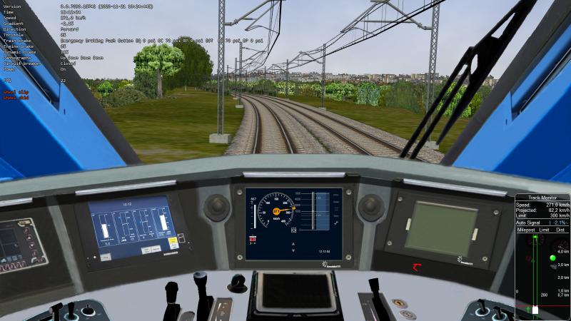
This is an idea of what is available today:
DMI under national system, just before switch to ETCS L2, radio link already established
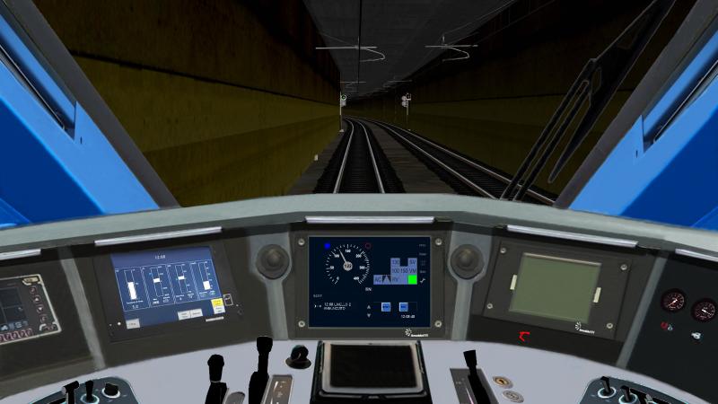
Under ETCS L2, braking needed
The trainset is the four-current ETR400, which, if Covid allows that, should circulate in next years also in France and Spain and accepts also the 15kV used in the German-speaking countries.
DMI under national system, just before switch to ETCS L2, radio link already established
Under ETCS L2, braking needed
The trainset is the four-current ETR400, which, if Covid allows that, should circulate in next years also in France and Spain and accepts also the 15kV used in the German-speaking countries.
#5
- Engineer
-
- Group: Posts: Contributing Member
- Posts: 587
- Joined: 30-March 20
- Gender:Male
- Simulator:Open Rails
-
Country:
Posted 17 November 2020 - 12:51 PM
I attach a demonstration of ETCS operation in OR with the external DMI: https://youtu.be/UjgDJ5q1BNU
Something similar will be achieved by drawing the DMI in the cabview, but in a much cleaner and user-friendly way. I'll start learning the basics of Monogame and I hope I can show some results soon.
Something similar will be achieved by drawing the DMI in the cabview, but in a much cleaner and user-friendly way. I'll start learning the basics of Monogame and I hope I can show some results soon.
#6
- Member, Board of Directors
-
- Group: Posts: Elite Member
- Posts: 7,463
- Joined: 31-December 11
- Gender:Male
-
Country:
Posted 17 November 2020 - 01:43 PM
That looks good! Of course the definition of the in-cab display, as can be seen in my pictures, is a bit scarce and requires a decent monitor resolution (I have a 1600 x 900 monitor); 2048 horizontal pixels would be better, however I think that the result is sufficient. I also slightly widened the dimension of the DMI display to improve resolution. available.
What is missing in what I have done is also the braking distance square, which would be possible with conventional MSTS-like design only using many frames with squares of different measures. Here too a coded solution can simply provide a better result.
What is missing in what I have done is also the braking distance square, which would be possible with conventional MSTS-like design only using many frames with squares of different measures. Here too a coded solution can simply provide a better result.
#7
- Superintendant
-
- Group: Posts: Elite Member
- Posts: 1,561
- Joined: 25-September 17
- Gender:Male
- Simulator:Open Rails
-
Country:

Posted 18 November 2020 - 12:03 AM
For those of us barely catching up with the present day is there any difference between ETCS and ERTMS?
#8
- Member, Board of Directors
-
- Group: Posts: Elite Member
- Posts: 7,463
- Joined: 31-December 11
- Gender:Male
-
Country:
Posted 18 November 2020 - 01:17 AM
As far as I know ETCS (European train control system) is a subset of ERTMS (European rail traffic management system). As I read in a book by Lars Schnieder "An introduction to ETCS", "The main components of ERTMS are the train control system (ETCS) and digital mobile ommunication system (GSM-R)." I believe this is a bit rough, but it gives an idea.
#9
- Engineer
-
- Group: Posts: Contributing Member
- Posts: 587
- Joined: 30-March 20
- Gender:Male
- Simulator:Open Rails
-
Country:
Posted 18 November 2020 - 06:42 AM
I've already made some progress. The conversion from C++ is being quite simple, with the exception of font drawing.
In my 1366x768 laptop the digits are hardly seen, as Carlo said. I'm not an expert in graphics, but it would be awesome to have some kind of zooming function to see the DMI console.
In my 1366x768 laptop the digits are hardly seen, as Carlo said. I'm not an expert in graphics, but it would be awesome to have some kind of zooming function to see the DMI console.
Attached thumbnail(s)
#10
- Engineer
-
- Group: Posts: Contributing Member
- Posts: 587
- Joined: 30-March 20
- Gender:Male
- Simulator:Open Rails
-
Country:
Posted 18 November 2020 - 07:49 AM
I have one question for developers experienced with OR graphics: what should I do to add ETCS symbols to the Content folder and load them from there?
Edit: I'm using SharedTextureManager.Get() like for TrackMonitor, but I have to copy the symbols to the Content folder by hand.
Edit: I'm using SharedTextureManager.Get() like for TrackMonitor, but I have to copy the symbols to the Content folder by hand.
#11
- Engineer
-
- Group: Posts: Contributing Member
- Posts: 587
- Joined: 30-March 20
- Gender:Male
- Simulator:Open Rails
-
Country:
Posted 20 November 2020 - 01:16 AM
I have created a branch on GitHub with a first working version of the planning window. It's aligned with OR NewYear MG. https://github.com/c...s/tree/etcs_dmi
It is rendered using the same cabview control that was used for the CircularSpeedGauge, just for testing.
A quick way to test it is using the default MSTS script, which I have modified to show the new DMI features.
Regarding the API, I have created a dedicated ETCSStatus class accessible from the TCS, but this can be changed if there's a more convenient way to do it.
I have found some issues due to floating point to integer round errors when downscaling the components, so bad-looking areas will appear with low resolution screens or small DMI area in cab.
It is rendered using the same cabview control that was used for the CircularSpeedGauge, just for testing.
A quick way to test it is using the default MSTS script, which I have modified to show the new DMI features.
Regarding the API, I have created a dedicated ETCSStatus class accessible from the TCS, but this can be changed if there's a more convenient way to do it.
public class ETCSStatus
{
    // General status
    public bool DMIActive = true;
    ...

    // Speed and distance monitoring
    ...

    // Planning information
    public bool PlanningAreaShown = true;
    public List<PlanningTarget> SpeedTargets = new List<PlanningTarget>();
    public PlanningTarget? IndicationMarkerTarget;
    public float? IndicationMarkerDistanceM;
    public List<GradientProfileElement> GradientProfile = new List<GradientProfileElement>();

    public ETCSStatus Clone()
    {
        // Clone all elements and lists so they can be accessed safely by RenderProcess
    }
}
public struct PlanningTarget
{
    public float DistanceToTrainM;
    public readonly float TargetSpeedMpS;
    public PlanningTarget(float distanceToTrainM, float targetSpeedMpS)
    {
         DistanceToTrainM = distanceToTrainM;
         TargetSpeedMpS = targetSpeedMpS;
    }
}
public struct GradientProfileElement
{
    public float DistanceToTrainM;
    public int GradientPerMille;
}
I have found some issues due to floating point to integer round errors when downscaling the components, so bad-looking areas will appear with low resolution screens or small DMI area in cab.
#12
- Member, Board of Directors
-
- Group: Posts: Elite Member
- Posts: 7,463
- Joined: 31-December 11
- Gender:Male
-
Country:
Posted 20 November 2020 - 08:39 AM
Hi César,
thank you very much! I'll try now to apply to the ETR400 what you have kindly created, by inserting your code first as a branch into OR NewYear MG, and then merging it (if you agree of course).
I'll report about the results.
thank you very much! I'll try now to apply to the ETR400 what you have kindly created, by inserting your code first as a branch into OR NewYear MG, and then merging it (if you agree of course).
I'll report about the results.
#13
- Member, Board of Directors
-
- Group: Posts: Elite Member
- Posts: 7,463
- Joined: 31-December 11
- Gender:Male
-
Country:
Posted 21 November 2020 - 02:09 AM
Hi César,
you've done a fast and great job! I've appreciated also very much the possibility of disabling the display of the planning area, which I need when the train is running on a part of route equipped with the national TCS.
Here a picture
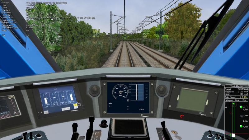
I only notice that the external maxspeed ring of the tacho touches the distance numbers of the planning area; there is also a strange small black area on the right of the tacho between the tacho itself and the maxspeed ring, but they are really minor things. Maybe I have to respect some rule in defining the ratio between width and height of the control?
I wonder what your intentions are now: will you add other info to such area, or will you leave it so?
What do you suggest to find out next elevation profile segments? I'm thinking at another list to be conditionally (only with Planning area shown) generated within the UpdatePlayerTrainData() method.
Thank you again!
you've done a fast and great job! I've appreciated also very much the possibility of disabling the display of the planning area, which I need when the train is running on a part of route equipped with the national TCS.
Here a picture
I only notice that the external maxspeed ring of the tacho touches the distance numbers of the planning area; there is also a strange small black area on the right of the tacho between the tacho itself and the maxspeed ring, but they are really minor things. Maybe I have to respect some rule in defining the ratio between width and height of the control?
I wonder what your intentions are now: will you add other info to such area, or will you leave it so?
What do you suggest to find out next elevation profile segments? I'm thinking at another list to be conditionally (only with Planning area shown) generated within the UpdatePlayerTrainData() method.
Thank you again!
#14
- Engineer
-
- Group: Posts: Contributing Member
- Posts: 587
- Joined: 30-March 20
- Gender:Male
- Simulator:Open Rails
-
Country:
Posted 21 November 2020 - 03:15 AM
I have to add the track conditions (non stopping area, close air intake, neutral section, etc.) to the left side of the planning window, as well as the zooming functions. I've seen you have implemented the distance to target bar, but I can add it to the code so it's easier to add ETCS to more cabviews, if you like so. I will try to add the text message area too.
There seems to be a problem with the shader, because the gauge is doing something weird after 200km/h. I'll look at it. Did this happen in previous versions?
I used a wrong font size for distance scale numbers, they are bigger than they should. Thanks for pointing it.
There seems to be a problem with the shader, because the gauge is doing something weird after 200km/h. I'll look at it. Did this happen in previous versions?
I used a wrong font size for distance scale numbers, they are bigger than they should. Thanks for pointing it.
#15
- Member, Board of Directors
-
- Group: Posts: Elite Member
- Posts: 7,463
- Joined: 31-December 11
- Gender:Male
-
Country:
Posted 21 November 2020 - 03:21 AM
Here with a bit more data shown