Elvas Tower: Wishes for improvement of braking systems - Elvas Tower

Jump to content

  • 67 Pages +
  • « First
  • 60
  • 61
  • 62
  • 63
  • 64
  • Last »
  • You cannot start a new topic
  • You cannot reply to this topic

Wishes for improvement of braking systems Adding and correcting of features Rate Topic: -----

#611 User is offline   pschlik 

  • Conductor
  • Group: Status: Active Member
  • Posts: 354
  • Joined: 04-March 15
  • Gender:Male
  • Simulator:OpenRails - Unstable
  • Country:

Posted 07 February 2024 - 09:41 AM

View PostTraindude, on 06 February 2024 - 04:18 PM, said:

From what I can tell, the "main reservoir pipe" is only there to convey MR air to cab/control cars on the opposite end of the consist. For now, the "Twin Pipe Air" system used with the original MSTS Acela and HHP-8 is the closest we have to this.


Not quite, some of the older stock is like that but on the newer Superliners/Amfleets there's a dedicated (and quite large) supply reservoir for both the brakes and other hardware that needs air. Normally that is charged from the main res pipe but will take from the brake pipe if that's at higher pressure. That's something I can look into implementing, it shouldn't be too hard to set up and would be more realistic than feeding the aux res directly off the main res pipe.

View PostTraindude, on 06 February 2024 - 04:18 PM, said:

Also, has there been any work in regard to why adding "Distributing_Valve" to a locomotive with a 6ET or 8ET brake system causes the brake pipe to drain completely after the brake handle has been lapped?


Don't see any reason why the distributing valve would change anything about the brake pipe, the only difference in behavior that has from the regular triple valve has to do with locomotive brake cylinder behavior. Could be a confounding factor with something else in the engine file.

#612 User is offline   pschlik 

  • Conductor
  • Group: Status: Active Member
  • Posts: 354
  • Joined: 04-March 15
  • Gender:Male
  • Simulator:OpenRails - Unstable
  • Country:

Posted 14 February 2024 - 09:03 PM

Made another change, added supply reservoirs. To use a supply reservoir, add Supply_Reservoir to the list of 'BrakeEquipmentType' in the wagon. Set the volume of the supply reservoir using ORTSSupplyResCapacity and the rate at which it charges from the brake pipe (or MR pipe on twin pipe systems) using ORTSSupplyResChargingRate. If the supply reservoir should charge from the brake pipe even on twin pipe systems (perhaps the MR pipe is merely a pass-through connection), then use ORTSMainResPipeAuxResCharging ( 0 )


The supply reservoir will be used to pressurize the brake cylinders instead of the auxiliary reservoir (the aux res is still required to determine what pressure should be sent to the brake cylinders), which allows the auxiliary reservoir to be much smaller than usual, and that helps to speed up brake pipe recharge times. It's worthwhile to double-check your brake cylinder volume and aux res volume if a supply res is going to be used. Supply res is also pretty important for wheel slide protection, as it provides a constant supply of air from the brake pipe to refill the brake cylinders after being vented by an anti-slide system.

#613 User is offline   Traindude 

  • Engineer
  • Group: Status: Contributing Member
  • Posts: 664
  • Joined: 17-November 13
  • Gender:Male
  • Location:Seattle, WA
  • Simulator:Open Rails
  • Country:

Posted 15 February 2024 - 12:30 PM

View Postpschlik, on 07 February 2024 - 09:41 AM, said:

Don't see any reason why the distributing valve would change anything about the brake pipe, the only difference in behavior that has from the regular triple valve has to do with locomotive brake cylinder behavior. Could be a confounding factor with something else in the engine file.


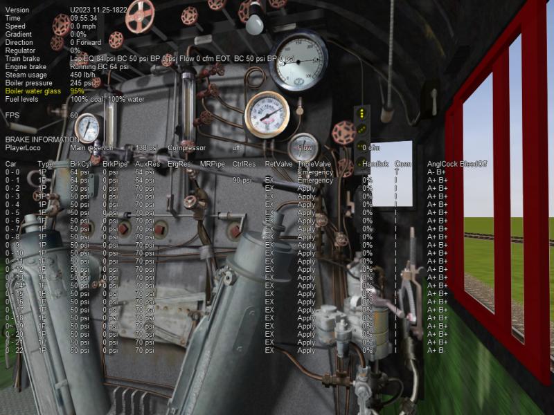
Darwin and I discovered this when attempting to emulate 6/6ET braking systems to update the CTN US Steam locomotives. Since these systems really don't have triple valves, it made sense to omit the triple valves, and instead list "Distributing_valve". However, when we tested this in-game, it caused the brake pipe to completely drain, even after the brake handle had been lapped:
Attached Image: Open Rails 2023-11-26 11-02-51.jpg

You can see that even though the brake handle is in the lap position, and the EQ pressure is 84 PSI, the brake pipe has dropped to zero.

Here are the settings I used:
 BrakeEquipmentType( "Distributing_valve, Auxilary_reservoir" )
       BrakeSystemType( "Air_single_pipe" )


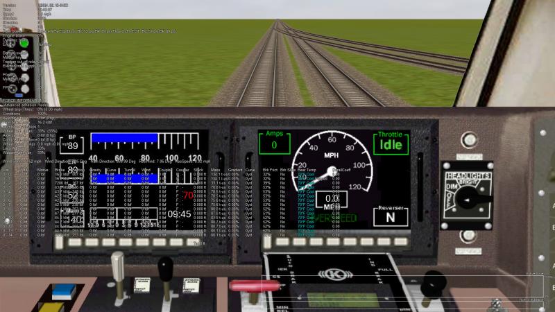
Also, while trying to emulate the braking system for the Amtrak Superliners, I decided to try using "Disc_Pads" as the ORTSBrakeShoeType. However, when testing this in-game, the results were not good. The brake friction display in the extended HUD gave a different friction coefficient percentage for each car, depending on the weight of the car.:
Attached Image: Open Rails 2024-02-15 12-19-52.jpg

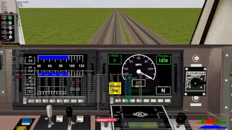
Furthermore, whenever the brake cylinder pressure changes, there are some rather bizarre side effects:
Attached Image: Open Rails 2024-02-15 12-21-05.jpg

Changing the brake shoe type to "Hi_Friction_Composite" remedied all this.

The question is...is this supposed to be normal for disc brake pads? If not, then we have some serious issues to work out!

#614 User is offline   pschlik 

  • Conductor
  • Group: Status: Active Member
  • Posts: 354
  • Joined: 04-March 15
  • Gender:Male
  • Simulator:OpenRails - Unstable
  • Country:

Posted 15 February 2024 - 06:24 PM

View PostTraindude, on 15 February 2024 - 12:30 PM, said:

Darwin and I discovered this when attempting to emulate 6/6ET braking systems to update the CTN US Steam locomotives. Since these systems really don't have triple valves, it made sense to omit the triple valves, and instead list "Distributing_valve". However, when we tested this in-game, it caused the brake pipe to completely drain, even after the brake handle had been lapped:
Attachment Open Rails 2023-11-26 11-02-51.jpg

You can see that even though the brake handle is in the lap position, and the EQ pressure is 84 PSI, the brake pipe has dropped to zero.

Here are the settings I used:
 BrakeEquipmentType( "Distributing_valve, Auxilary_reservoir" )
   	BrakeSystemType( "Air_single_pipe" )

Hmm, does that still happen on the current unstable version? Right now the only way a locomotive will reduce the brake pipe pressure is if the equalizing reservoir pressure is below the brake pipe pressure (still need to investigate support for systems with no equalizing res), the train brake controller is in emergency (or an emergency vent valve has opened), or the locomotive has been configured with a brake pipe leak. Maybe you set a very high brake pipe leak rate, I can't tell from here.

View PostTraindude, on 15 February 2024 - 12:30 PM, said:

Also, while trying to emulate the braking system for the Amtrak Superliners, I decided to try using "Disc_Pads" as the ORTSBrakeShoeType. However, when testing this in-game, the results were not good. The brake friction display in the extended HUD gave a different friction coefficient percentage for each car, depending on the weight of the car.:
Attachment Open Rails 2024-02-15 12-19-52.jpg

Furthermore, whenever the brake cylinder pressure changes, there are some rather bizarre side effects:
Attachment Open Rails 2024-02-15 12-21-05.jpg

Changing the brake shoe type to "Hi_Friction_Composite" remedied all this.

The question is...is this supposed to be normal for disc brake pads? If not, then we have some serious issues to work out!

First, the brake friction isn't varying with weight it varies with the amount of brake force (which you have configured to change with weight). Now...you have your brake forces set way too high for superliners. But the brake shoe friction calculation definitely has problems, the friction goes negative at 24.5 kN of brake shoe force, then has a vertical asymptote at 27.2 kN of brake shoe force. This obviously makes no sense, but 20-something kN is an insane force for a single brake shoe...I'm not surprised the prediction fails. (For context, I'm using a brake shoe force of around 250 kN @ 100 psi for a superliner...spread across 24 brake shoes.) Still, perhaps some checks need to be implemented to disallow negative brake friction. Or maybe just disregard any calculation for a brake shoe force above about 20 kN. Peter did the implementation for the brake shoe friction curves and I'd rather not mess with it when he's still a contributing member.

https://i.imgur.com/VVliR47.png

#615 User is offline   Traindude 

  • Engineer
  • Group: Status: Contributing Member
  • Posts: 664
  • Joined: 17-November 13
  • Gender:Male
  • Location:Seattle, WA
  • Simulator:Open Rails
  • Country:

Posted 15 February 2024 - 11:46 PM

View Postpschlik, on 15 February 2024 - 06:24 PM, said:

(For context, I'm using a brake shoe force of around 250 kN @ 100 psi for a superliner...spread across 24 brake shoes.)


I took your suggestions, and by using the same braking force for all my Superliners, the brakes work properly.

#616 User is offline   pschlik 

  • Conductor
  • Group: Status: Active Member
  • Posts: 354
  • Joined: 04-March 15
  • Gender:Male
  • Simulator:OpenRails - Unstable
  • Country:

Posted 17 February 2024 - 10:41 PM

Put up another version with some other features I researched. Nothing too crazy, just some extra options that should expand the capabilities of relay valves.

  • ORTSTwoStageRelayValveRatio: Unitless quantity, works with the two stage braking system. In the 'slow' speed regime, this defines the relay valve ratio that will be used by the automatic brakes, overriding whatever ratio was set by ORTSBrakeRelayValveRatio. This will probably be more accurate than using ORTSTwoStageLowPressure for some systems, as it can reduce the brake cylinder pressure applied at all levels of brake application, instead of just lowering the pressure of a strong application.
  • ORTSBrakeRelayValveInshot: Units of pressure, requires relay valve. If you do enough digging you might learn about 'in-shot', a feature of some relay valves (usually ones with a relay valve ratio less than 1.0) that adds extra brake cylinder pressure to the output of the relay valve. This is usually done to make sure the brake cylinders extend fully even with light brake applications. As an example, if you have "ORTSBrakeRelayValveRatio ( 0.4 )" and the triple valve outputs 10 psi, this relay valve will send only 4 psi to the brake cylinders. 4 psi probably won't give you any brake friction (remember, use ORTSCylinderSpringPressure to set the minimum pressure that gives friction). Meanwhile, with a full 64 psi application, the brake cylinder gets 26 psi, which is fine. However, if you add "ORTSBrakeRelayValveInshot ( 5 psi )", the triple valve output of 10 psi translates into 9 psi (4 psi + 5) at the brake cylinders, which will probably be enough to get the brake shoes touching the wheels. The extra 5 psi will be added across the entire operating range, so with a full application this would give you 31 psi (26 psi + 5). This is a really in the weeds detail but it shows up in a lot of places.
  • ORTSEngineBrakeRelayValveInshot: Same as the previous one, but ignores automatic brake applications and instead works on locomotive brake applications.


#617 User is online   darwins 

  • Superintendant
  • Group: Status: Elite Member
  • Posts: 1,250
  • Joined: 25-September 17
  • Gender:Male
  • Simulator:Open Rails
  • Country:

Posted 18 February 2024 - 01:11 AM

Should you add the inshot to all values? The purpose of an inshot as you said is to make sure that initial application is strong enough to apply the brake shoes or pads.

I am thinking:

1. If brake pipe reduction is less than "minimum reduction" required to apply brakes - due to leakage or possible by manual application in older systems then nothing happes - the reduction is ignored, no inshot, no effect of relay ratio.

2. Whatever "minimum reduction" pressure change applies the brakes results in an equivalent inshot that ensures an effective initial application.
(The relay ratio is ignored if it gives a pressure less than the inshot).

3. When the pressure due to the relay ratio is greater than the inshot then the BC pressure continues to rise according to the relay ratio until it reaches the maximum determined by the relay ratio.


If you add the inshot onto the relay ratio then the maximum will be greater than that determined by the relay ratio which does not seem right...

#618 User is offline   pschlik 

  • Conductor
  • Group: Status: Active Member
  • Posts: 354
  • Joined: 04-March 15
  • Gender:Male
  • Simulator:OpenRails - Unstable
  • Country:

Posted 18 February 2024 - 08:27 AM

The way I have implemented it is exactly how it works in real life. Many of these step-down relay valves have two chambers for the input pressure, one chamber having 100% the area of the output, and the other chamber having an area corresponding to the relay valve ratio (the J-16-B has a second chamber with 60% the area of the output). When a brake application is sent to the relay valve, air is sent directly to the smaller 60% chamber, while air to the 100% chamber goes through the in-shot portion first, limiting the pressure in the 100% chamber to 5 psi in this case.

The result of this is that the output (brake cylinder) pressure required to overcome the input pressure and lap the brakes will be 60% of the pressure in the 60% chamber plus 100% of the pressure in the 100% chamber (ie: 60% of the input pressure + 5 psi).

That does mean the effective relay valve ratio is not the ratio printed on the tin. Look at the J-64B relay valve; this one claims to apply 60% locomotive brake pressure (locomotive brake control signal goes from 0 to 45 psi) or 40% of train brake pressure (which will be 64 psi at full service). If we go off these ratios, then the expected full locomotive brake pressure is 45 * 0.6 = 27 psi and full service pressure is 64 * 0.4 = 25.6 psi. Now if we look at the pressure that actually results...
https://i.imgur.com/1K7qgfY.png
Oh...look at that, 32 psi of brake cylinder pressure both in full loco brake application and at full service. 32 - 27 = 5...5 extra psi are added above the true relay valve ratio. That is no coincidence, in-shot is responsible for the extra pressure (and we know in-shot is present here because of the "B" suffix in the relay valve designation). For the automatic brake applications, this extra pressure is about 6 psi instead. Some relay valves have in-shot on just the train brakes but not the loco brakes. The two separate settings are needed to cover these cases.

#619 User is online   darwins 

  • Superintendant
  • Group: Status: Elite Member
  • Posts: 1,250
  • Joined: 25-September 17
  • Gender:Male
  • Simulator:Open Rails
  • Country:

Posted 19 February 2024 - 04:22 AM

Quote

still need to investigate support for systems with no equalizing res


I still need to catch up with the dozens of new features you have added recently and how to use them!! https://www.elvastower.com/forums/public/style_emoticons/default/sweatingbullets.gif

When you do get round to systems without equalizing reservoirs then you might want to look at the code for vacuum brakes. Most vacuum brake systems did not have an equalizing reservoir. This has already been simulated with a moderate degree of success in OR. When the driver lets a certain volume of air out then the air remaining in the train pipe spreads out evenly, reducing the previous pressure at the rear of the train but causing the new low pressure at the front to rise at the same time until it is even all along the pipe.

In UK the London Brighton and South Coast Railway operated systems without equalising reservoirs and with manually controlled compressors until the end of its existence. Presumably they did not wish to pay extra for the most recent Westinghouse products!

#620 User is offline   pschlik 

  • Conductor
  • Group: Status: Active Member
  • Posts: 354
  • Joined: 04-March 15
  • Gender:Male
  • Simulator:OpenRails - Unstable
  • Country:

Posted 09 March 2024 - 02:40 PM

These changes had to leave unstable for a moment but are back now. Also, some new features I'd like folks to check out.
  • psi/min and bar/min can be used as pressure units now, this should help for those cases where you want to enter a very slow rate of pressure transfer
  • I did research and found that there are some types of in-shot that override the demanded pressure, so the brake cylinder pressure ends up being the max of the demanded pressure or the inshot pressure. To use that alternate mode, enter a negative pressure as inshot. ORTSBrakeRelayValveInshot ( -10psi ) wouldn't subtract 10 psi, it would give a pressure equal to the demanded pressure or 10 psi, whichever is greater. The negative thing doesn't have any real life equivalent, it's just simpler than adding even more tokens.
  • New ways to define brake cylinder volume. ORTSBrakeCylinderDiameter lets you enter the diameter of the brake cylinder, ORTSBrakeCylinderPistonTravel for the stroke of the brake cylinder (assumed to be 8 inches by default), and ORTSBrakeCylinderPipingVolume to define any additional volume attached to the brake cylinder (if you don't know what this should be, it will be estimated automatically). The volume will then be calculated automatically and multiplied by ORTSNumberBrakeCylinders if the car has more than one brake cylinder. This should be easier than manually doing the calculations and will allow for a more accurate brake cylinder simulation soon.
  • You can also manually define the auxiliary res volume now, with ORTSAuxiliaryResCapacity. Doesn't behave any different than if it was defined based on the emergency res volume but should make things a bit easier, especially on cars that don't have emergency reservoirs in the first place! Always felt a bit silly needing to define the emergency reservoir volume for an emergency reservoir that simply isn't real.


  • 67 Pages +
  • « First
  • 60
  • 61
  • 62
  • 63
  • 64
  • Last »
  • You cannot start a new topic
  • You cannot reply to this topic

2 User(s) are reading this topic
0 members, 2 guests, 0 anonymous users