Log In
 Register Now!
 Help
Help


How do we model them? How do we set up the physics?
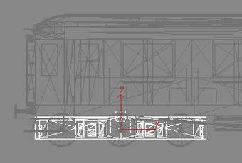
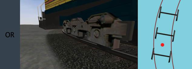
Consider a 3 axle car, 9m in length with 6m wheelbase. In real life it could certainly negotiate curves of less than 100m radius, so I have made some illustrations based on a 60m radius curve.
Firstly the situation in real life, the ability to negotiate curves depends (mostly) on having some sideplay of the axles:
https://i.imgur.com/5hC8gqP.jpg
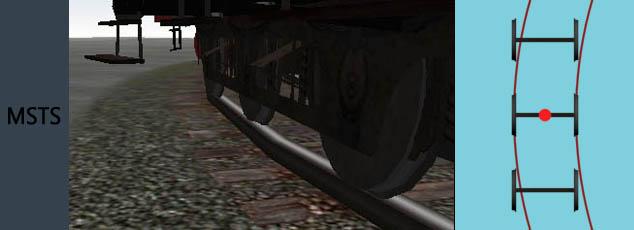
The rigid wheelbase doesn't quite work in MSTS or OpenRails as there is no sideways movement of wheels and axles.
https://i.imgur.com/ywssEt6.jpg
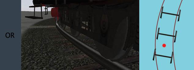
So the conventional MSTS and OR modelling solution was to create two false bogies. Each bogie is pivoted 1.5m from the centre axle. One bogie has two pairs of wheels, whilst the other bogie has only one pair of wheels. The visual effect is better:
https://i.imgur.com/XlitJ1x.jpg
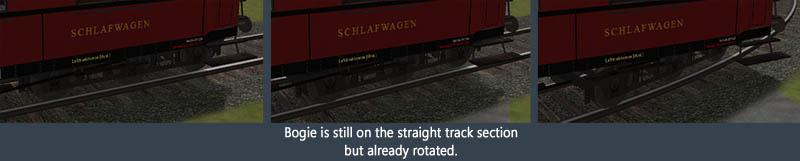
Another option is now available in OR. We can have more than two bogies. What would happen if we used three bogies with the bogie pivot at the centre of each axle? Would the result be better or worse than the previous suggestion? Would it look something like this?
https://i.imgur.com/IGJW819.jpg
The model and the physics do not have to be the same. We might use any of the following options
ORTSNumberBogies ( 0 )
ORTSNumberBogies ( 1 )
	ORTSNumberBogies ( 2 )
	ORTSLengthBogieCentre ( 3m )
	ORTSNumberBogies ( 3 )
	ORTSLengthBogieCentre ( 3m )
	ORTSNumberBogies ( 3 )
	ORTSLengthBogieCentre ( 6m )
In all of these cases I am assuming that
	ORTSNumberAxles ( 4 )
	ORTSRigidWheelbase ( 6m )
is appropriate. What do others think? Is there a "correct" solution for rolling stock with a long rigid or semi-rigid wheelbase?