Elvas Tower: 6 wheeled vehicles - Elvas Tower

Jump to content

  • 2 Pages +
  • 1
  • 2
  • You cannot start a new topic
  • You cannot reply to this topic

6 wheeled vehicles How do we handle long rigid wheelbase? Rate Topic: ***** 1 Votes

#11 User is offline   Jonatan 

  • Vice President
  • Group: Status: Elite Member
  • Posts: 2,662
  • Joined: 29-March 10
  • Gender:Male
  • Location:Somewhere.
  • Simulator:MSTS and Vehicle Simulator
  • Country:

Posted 29 November 2023 - 08:35 AM

View Postdarwins, on 28 November 2023 - 10:45 PM, said:

Flange lubricators should put grease only on the flange and not on the wheel tread!


Sometimes it happens, and then Roger's not pleased!
https://www.youtube....h?v=AIyilV7eGeI

#12 User is offline   jonas 

  • Engineer
  • Group: Status: Contributing Member
  • Posts: 548
  • Joined: 04-April 14
  • Gender:Male
  • Simulator:MSTS & OR
  • Country:

Posted 29 November 2023 - 05:45 PM

Thanks ErickC for the tip with the physics files. So I added these variables to the wagon's wag file:

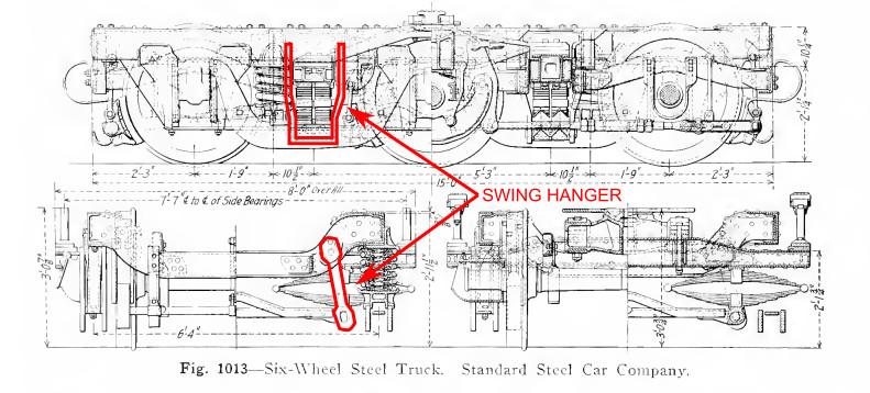
ORTSLengthBogieCentre ( 14 )
ORTSLengthCarBody ( 19.2 )
ORTSLengthCouplerFace ( 20,478 )
ORTSNumberAxles ( 6 )
ORTSNumberBogies ( 2 )

But unfortunately there was no change in the behavior of the wagon's bogies in the curve.


Attached Image: Post02_01.jpg
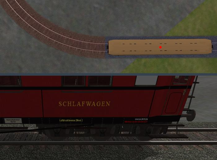
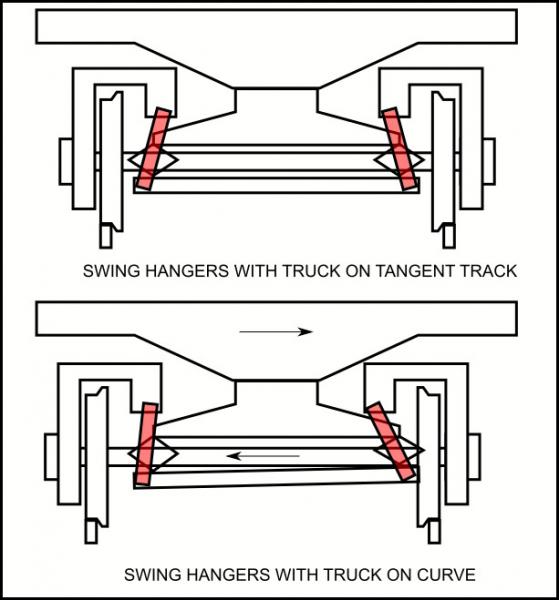
Everything is ok on the straight track.


Attached Image: Post02_02.jpg
One bogie is still on the straight track, but the car body has already entered the curve.
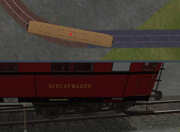
Of course, a rotation of the bogie relative to the car body is already correct here. But the bogie is "twisted" more than necessary.


Attached Image: Post02_03.jpg
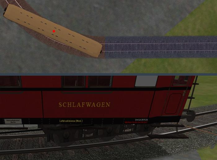
The entire wagon is on the curve.


Thanks Laci1959 for the tip that OR generally assumes 4 axles per bogie. At least that explains the specific bogie “twist”.
Attached Image: ORTS-3er-Drehgestell-Pivot.jpg
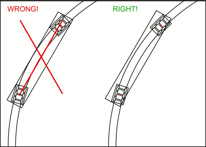
The pivot point of the bogie is actually calculated by OR between the second and third axles. So it is somewhere else as I set it in the model.


The rotation of a bogie is probably calculated in OR using the position of the car body pivot (red dot in the images) in the curve. So the specific position of the bogie pivot over the track vector is not taken into account, but only the car body pivot. Based on this, the rotation of the bogies is then calculated, depending on the position of the curve. In my opinion, there would be nothing wrong with that if the specific dimensions of the car body and bogies were taken into account. Unfortunately, specifying the dimensions, as mentioned above, did not help.

I have to admit without envy that MSTS works much better here. Apparently MSTS determines the pivots of the bogies defined in the model shape and then takes these into account with their respective positions over the track vectors.

As a car modeler, I am of course interested in this topic, but on the other hand I have to admit that I rarely pay attention to the exact curves of the bogies in the game. In addition, I tried it here for the screenshots with an extreme curve, the narrowest radius of the dynamic track. It is doubtful whether the bogie "over-rotation" would still be perceived as annoying even in gentle, wide curves with a larger radius.
Incidentally, I found the variables used above, such as ORTSNumberAxles, in the OR manual only under Derailment Coefficient, so they otherwise seem to have no intended effect on the adaption to the curve, but primarily play a role in derailment.

Coming back to the actual topic here, the programming implementation of laterally movable axles in curves seems to me to be quite ambitious - at least as long as it works as analyzed above. So an MSTS-like exact calculation of the exact bogie positions above the track would actually have to be carried out before one should then think about laterally movable axles - probably a more extensive programming construction site.

What I often observe when driving over switch roads is a short, tremble turning of bogies in general. Maybe this also has something to do with the bogie calculation using the car body center. So it's good that this topic was addressed here I think.

#13 User is offline   Traindude 

  • Engineer
  • Group: Status: Contributing Member
  • Posts: 664
  • Joined: 17-November 13
  • Gender:Male
  • Location:Seattle, WA
  • Simulator:Open Rails
  • Country:

Posted 29 November 2023 - 09:13 PM

I mentioned swing hangers in an earlier post. This may be of interest for this discussion.

A swing hanger is a device that allows the wheels of a truck (bogie) to shift laterally when a rail vehicle enters a curve at speed. It is most commonly found on locomotives, passenger cars, and even a few steam tenders. So, instead of the truck sideframes being connected directly to the bolster (via springs), the swing hangers connect the truck sideframes to a lateral intermediate transom, which is then connected to the truck bolster by means of the springs.

Attached Image: swinghanger1.jpg

Here's a basic illustration of how a swing hanger moves when entering a curve. Notice how the arcs described by the lower ends of the swing hangers tilt the transom, but this is absorbed by the leaf springs that connect the transom to the bolster.

Attached Image: swinghanger2.jpg

Here's what this action looks like from above. In the right-hand illustration, the green dots represent the pivot point of the truck bolsters (alligned with the longitudinal center line of the car body), while the red dots represent the center point of the wheelsets and truck frames.
Attached Image: swinghanger3.jpg

A temporary solution to simulate this would be to allow the pivot point of whole truck (and not just the axles) to shift laterally when entering a curve. When we finally get a new shape file format, we can possibly "rig" the various parts of the trucks (bolster, swing hangers, transom, springs, sideframes, etc.) using armatures and bones. (And if we really wanted to, then we could also rig the axles, springs and equalizers to we have a functioning suspension system!)

#14 User is offline   ErickC 

  • Superintendant
  • Group: Status: Elite Member
  • Posts: 1,004
  • Joined: 18-July 17
  • Gender:Male
  • Location:Hastings, MN, US
  • Simulator:ORTS
  • Country:

Posted 29 November 2023 - 10:50 PM

I initially misread your post as implying that swing hangers allow the center axle to move, which is in error. Apologies - I have eliminated the potion of this post where I discussed how swing hangers work. I think it would be beneficial for OR to have a way to specify a lower truck assembly that rotates and moves to follow the track as well as an upper truck assembly that only rotates. We should be able to specify if the lower assembly can translate laterally (e.g., for swing hanger trucks) or only vertically (e.g., for trucks without swing hangers).

Anyway, on the subject of how the center axle (or axles) on a truck with more than two axles interacts with curves, the basic fact is this: Lateral motion isn't going to come from wheel bearings and the only form of lateral motion comes from either radial trucks or equipment with other lateral motion devices as seen above. On a piece of equipment without those devices, either the center axle (or axles) must lack flanges, or the equipment will be restricted on curve radius.

The fact that the center axle doesn't have sideways movement without radial trucks or lateral motion devices in the real world has a negative impact on adhesion and is why EMD and GE developed radial trucks for locomotive applications in the first place. Sideways play in non-thrust bearings is a good way to destroy bearings, and, in fact, bearings for railway applications have dual races with opposing taper and are tightly mounted to the axle. This is what the bolts seen on the bearing caps are for, and the bearing assembly is also designed to fit in the sideframe in a way that eliminates transverse play. Even plain bearings have extremely limited to no lateral play because the bearing surface fits into a race cut into the axle:

Attached Image: bearing play.JPG

One final point of interest: in the real world, the gauge is typically widened somewhat in curves.

I agree that OR calculates truck rotation based on the center of the carbody, and I think this is also why curve force (and thus flange squeal) begin after a curve has already been entered.

#15 User is offline   Weter 

  • Member, Board of Directors
  • PipPipPipPipPipPipPipPipPipPip
  • Group: ET Admin
  • Posts: 6,993
  • Joined: 01-June 20
  • Gender:Not Telling
  • Simulator:ORTS
  • Country:

Posted 30 November 2023 - 12:16 PM

Indeed: 3-axle truck has an opportunity to shift relative carbodie's central axle to the right/left, and has mechanism, pulling it back on straight tracks, centering it.

#16 User is offline   JacobAbriß 

  • Apprentice
  • Group: Status: Dispatcher
  • Posts: 12
  • Joined: 01-December 23
  • Gender:Male
  • Location:USA
  • Simulator:MSTS, OR
  • Country:

Posted 02 December 2023 - 11:51 PM

View PostTraindude, on 28 November 2023 - 02:42 PM, said:

One more thing that should be noted is, regardless if the wheelsets are mounted in a ridgid frame or mounted in a truck/bogie, all rail wheelsets are given some degree of lateral "wiggle room" by having some lateral clearance between the journal box flanges and the frame. By the late steam era, many larger locomotives were equipped with lateral-motion devices that allowed for even more lateral than can be given by mere clearance between the journal box and the frame.

Attachment latmotion1.jpg
Attachment latmotion2.jpg

However, MSTS never accounted for this. If there was some way to make the axles shift their X-axis position away from zero when negotiating curves (with relevant parameters in *.wag or *.eng files) that would be great!

On the subject of curve resistance in general, many rail vehicles were equipped with wheel-flange lubricators to minimize the friction between the flange and the rail. Is the effect of flange lubrication something worth modelling?
Attachment flanglub.jpg


The Austrian engineer Karl Gölsdorf designed a few steam locomotives for the BBÖ with this sort of lateral movement, especially for the locos with 10 drivers, like the Gölsdorf 380 in base MSTS. As far as I can tell, no such feature was implemented in base MSTS. I'll see if I can dig up some diagrams for the Gölsdorf-Achse, though looking through German and Austrian patents is often very tedious. There is a Wikipedia article which affords a brief explanation, but no details of how the system actually works.

#17 User is offline   Lamplighter 

  • Fireman
  • Group: Status: Active Member
  • Posts: 171
  • Joined: 24-January 18
  • Gender:Male
  • Simulator:Open Rails
  • Country:

Posted 04 December 2023 - 03:27 AM

Many informative things about chassis, but also other parts of wagons can be found here.
Often with illustrative animation.

#18 User is offline   Jovet 

  • Open Rails Developer
  • Group: Status: Elite Member
  • Posts: 2,250
  • Joined: 14-January 08
  • Gender:Male
  • Location:Omaha, Nebraska.
  • Simulator:MSTS/Open Rails
  • Country:

Posted 04 December 2023 - 11:10 AM

This is a really interesting topic, and it's also intimidating as I am now quite glad I never tried to build a locomotive model myself.

  • 2 Pages +
  • 1
  • 2
  • You cannot start a new topic
  • You cannot reply to this topic

1 User(s) are reading this topic
0 members, 1 guests, 0 anonymous users