 Log In
 Register Now!
 Help
Help

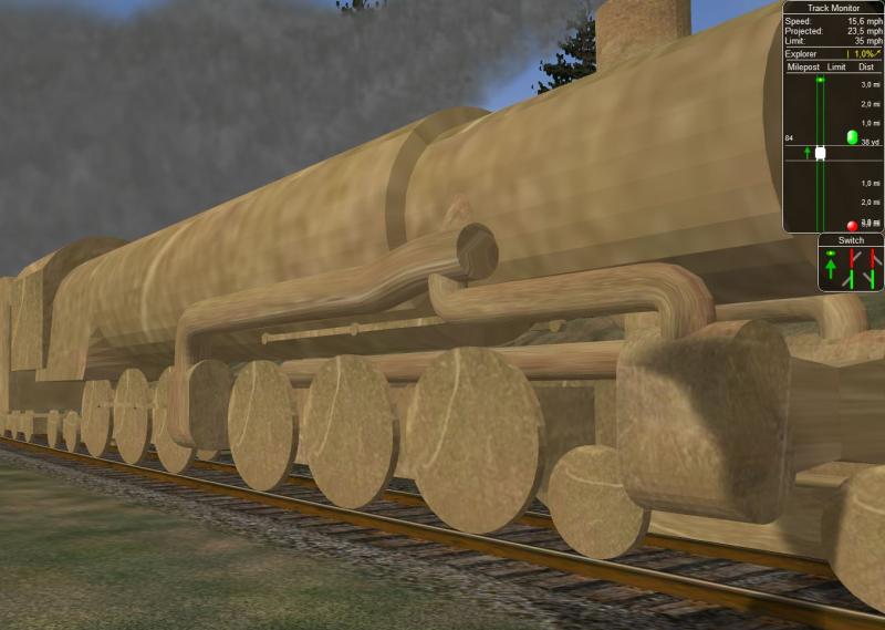
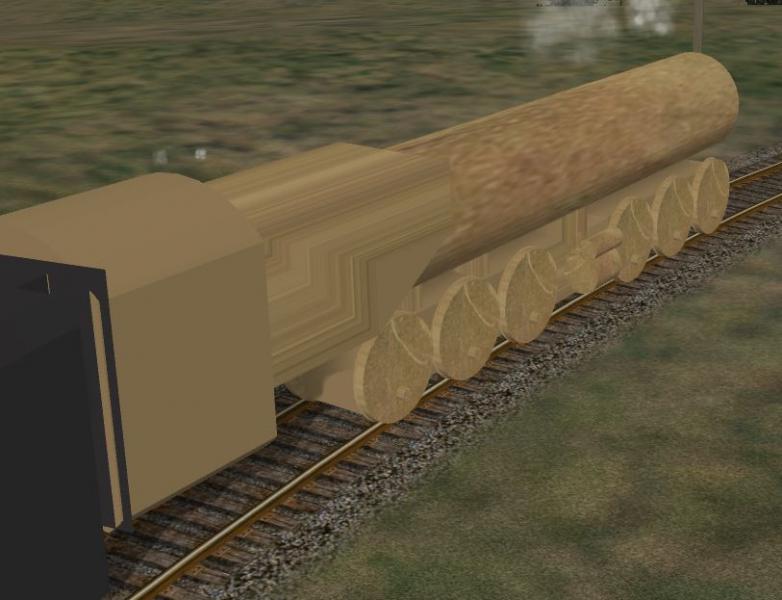
Hi. A while back there was a discussion of modelling articulated locomotives in OR as a single model instead of two or more sections. I decided to do some investigation of my own by building a test model of a 4-6-6-4 "Challenger" locomotive, with a matching tender. Believe it or not, the tender was the first thing I ever modeled in Blender with OR in mind! Here's a screenshot to prove that the locomotive is a single unit, and that the wheel arrangement is correct:
The model heirarchy for the Challenger has the following arrangement:
1. The rear half of the chassis is labeled MAIN
2. The front half of the chassis is labeled BOGIE1 and is parented to MAIN
3. The front set of driving wheels and their associated side rods are parented to BOGIE1
4. The rear set of driving wheels and their associated side rods are parented to MAIN in the usual manner
5. The 4-wheel leading truck is labeled BOGIE3 and is parented to BOGIE1
6. The 4-wheel trailing truck is labeled BOGIE2 and is parented to MAIN in the usual manner
At first OR had the tendency to throw the side rods for the front drive wheels out of vertical alignment, but I corrected this by manually editing the .s file.
Later, I experimented with creating the flexible steam pipes for the front cylinders by treating them as bogies. There are 3 of these pipes, one on each side of the smokebox (BOGIE5 for the engineer's side and BOGIE6 for the fireman's side) and a third pipe between and to the rear of the front cylinder saddle (BOGIE4). However, this is not without problems, as the outer steam pipes seem to separate on tight curves, such as the 125 meter curve on the CTN test route's Curve Branch. (illustrated below)
I have attached my test model, as well as the original Blender source files, for you guys to do some further experimentation.
Articulated Locomotive Test
Challenger Test Model
Rate Topic:

#1

- Engineer
-

- Group: Status: Contributing Member
- Posts: 662
- Joined: 17-November 13
- Gender:Male
- Location:Seattle, WA
- Simulator:Open Rails
-
Country:

Posted 18 September 2021 - 10:17 PM
#2
- Conductor
-

- Group: Status: Active Member
- Posts: 327
- Joined: 05-December 19
- Gender:Male
- Simulator:ORTS
-
Country:

Posted 17 April 2022 - 10:25 AM
I just compiled the blend files myself (version 2.83) without any changes and well... WHY??? :furious:
How is this possible and how do you made it work? I wanted to try fixing the hierachy by sticking the leading bogie directly to the MAIN, than it looks better in curves.
#3
- Engineer
-
- Group: Status: Contributing Member
- Posts: 662
- Joined: 17-November 13
- Gender:Male
- Location:Seattle, WA
- Simulator:Open Rails
-
Country:
Posted 18 April 2022 - 09:32 PM
 NickonWheels, on 17 April 2022 - 10:25 AM, said:
 48.JPG
I just compiled the blend files myself (version 2.83) without any changes and well... WHY??? :furious:
How is this possible and how do you made it work? I wanted to try fixing the hierachy by sticking the leading bogie directly to the MAIN, than it looks better in curves.
That's a bug that I'm afraid has no solution, most likely an issue with the Blender exporter. In this case, I suggest to manually adjust the front rods the uncompressed .s file in order to get them to stay in place. It turns out that the rods actually stay in place when they have rotation keyframes, it's only when there are location keyframes is there this misallignment occurs!
I have actually textured (still rather crudely) my model, and added some more details, and even made a 3D cab.
The new version is available for download below, and I have included instructions on how to reallign the rods after export.
#4
- Engineer
-
- Group: Status: Contributing Member
- Posts: 648
- Joined: 02-October 16
- Gender:Male
- Location:Chasetown
- Simulator:Openrails
-
Country:

Posted 19 April 2022 - 12:21 AM
What a super model! Thanks for sharing it.
You have done a great job on the 3d cab too.
Geoff
You have done a great job on the 3d cab too.
Geoff
#5
- Conductor
-
- Group: Status: Active Member
- Posts: 327
- Joined: 05-December 19
- Gender:Male
- Simulator:ORTS
-
Country:
Posted 20 April 2022 - 08:25 AM
Do you have the problem of shapeviewer not showing it?
#6
- Engineer
-
- Group: Status: Contributing Member
- Posts: 662
- Joined: 17-November 13
- Gender:Male
- Location:Seattle, WA
- Simulator:Open Rails
-
Country:
Posted 20 April 2022 - 05:29 PM
NickonWheels, on 20 April 2022 - 08:25 AM, said:
Do you have the problem of shapeviewer not showing it?
I use the TSRE Shape viewer and when I view the loco's .s file it does appear very far away. However, when viewing the .eng file via the TSRE Shape Viewer it appears at normal distance, even though the rods appear black instead of gray.
#7
- Conductor
-
- Group: Status: Active Member
- Posts: 327
- Joined: 05-December 19
- Gender:Male
- Simulator:ORTS
-
Country:
Posted 21 May 2022 - 12:09 PM
I made a few more tests.
Actually naming the leading bogie BOGIE3 does not have any effect on the sideways movement. The further away the EMPTY is from the subordinate MESH, the farther it 'derails' in curves. Placing both at the same location the swivel movement is good, but it can´t any longer move sideways.
In other words the is no lesser evil in trying to make a single unit in the current way ORTS handles the hierarchy.
A little idea of me is to have the EMPTY of both the front traction bogie and the leading bogie at the same level in hierarchy (and the same physical location of course).
In general it was a good idea to show but currently there can barely be motivation for modellers to make better models of articulateds, including diesels like U50 or electrics like Little Joe. Indeed I like to, but it´s discouraging for the time being.
#8
- Engineer
-
- Group: Status: Contributing Member
- Posts: 662
- Joined: 17-November 13
- Gender:Male
- Location:Seattle, WA
- Simulator:Open Rails
-
Country:
Posted 21 May 2022 - 01:03 PM
NickonWheels, on 21 May 2022 - 12:09 PM, said:
I made a few more tests.
Actually naming the leading bogie BOGIE3 does not have any effect on the sideways movement. The further away the EMPTY is from the subordinate MESH, the farther it 'derails' in curves. Placing both at the same location the swivel movement is good, but it can´t any longer move sideways.
In other words the is no lesser evil in trying to make a single unit in the current way ORTS handles the hierarchy.
A little idea of me is to have the EMPTY of both the front traction bogie and the leading bogie at the same level in hierarchy (and the same physical location of course).
In general it was a good idea to show but currently there can barely be motivation for modellers to make better models of articulateds, including diesels like U50 or electrics like Little Joe. Indeed I like to, but it´s discouraging for the time being.
Actually naming the leading bogie BOGIE3 does not have any effect on the sideways movement. The further away the EMPTY is from the subordinate MESH, the farther it 'derails' in curves. Placing both at the same location the swivel movement is good, but it can´t any longer move sideways.
In other words the is no lesser evil in trying to make a single unit in the current way ORTS handles the hierarchy.
A little idea of me is to have the EMPTY of both the front traction bogie and the leading bogie at the same level in hierarchy (and the same physical location of course).
In general it was a good idea to show but currently there can barely be motivation for modellers to make better models of articulateds, including diesels like U50 or electrics like Little Joe. Indeed I like to, but it´s discouraging for the time being.
I kinda agree with you, there's still a lot of refinement for conventional locomotives that needs to be done before we start fine-tuning articulateds. My hope was (and still is) to serve as a jumping-off point should the ORTS development team wish to refine articulateds in the future.
#9
- Conductor
-
- Group: Status: Active Member
- Posts: 327
- Joined: 05-December 19
- Gender:Male
- Simulator:ORTS
-
Country:
Posted 22 May 2022 - 01:19 AM
I started to make an artidculated like yours, but it´s painful. Not only modelling itself, but the hierarchy is causing trouble where I never encountered some before. ORTS thinks there are no wheels here and the bogie is not swivelling.
 4664test.zip (193.58K)
Number of downloads: 238
4664test.zip (193.58K)
Number of downloads: 238
#10
- Engineer
-
- Group: Status: Contributing Member
- Posts: 662
- Joined: 17-November 13
- Gender:Male
- Location:Seattle, WA
- Simulator:Open Rails
-
Country:
Posted 22 May 2022 - 09:17 PM
NickonWheels, on 22 May 2022 - 01:19 AM, said:
I started to make an artidculated like yours, but it´s painful. Not only modelling itself, but the hierarchy is causing trouble where I never encountered some before. ORTS thinks there are no wheels here and the bogie is not swivelling.
4664test.zip
55.JPG
4664test.zip 55.JPGIf you're having trouble with the hierarchy, here's the way I set up mine originally.:
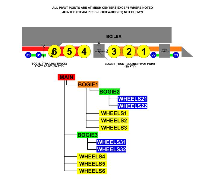
Note that the front engine (BOGIE1) has its pivot at a point at the lateral centerline of the rear cylinder block (as it usually is in the real world). Also note that on the trailing truck, as is typical with trailing trucks, even on 4-wheel trucks, the pivot point is in front of the front truck wheel instead of in the center.:
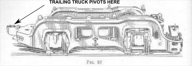
I did, however, move the lead truck pivot backwards later on, in recognition of the rocking bolster arrangement that is typical for 4-wheel lead trucks:
...And here's what it looks like going around a curve:
...however, in the end I decided to leave the lead truck pivot in the center of BOGIE2.
Hope this information helps.