 Log In
 Register Now!
 Help
Help
Hello,
I have been having issues using the embankment / cutting tools in TSRE so much so I have had to revert to using MSTS RE for some operations. I cannot seem to get the embankments / cuttings to behave as required. Either using the "F"key does nothing, or produces some very queer results.
A video below to show what I'm facing
https://youtu.be/ouht6Fz2onY
Anyone else facing similar issues? Its happening on 2 routes now. If I'm doing something wrong please let me know :(
Thanks.
Page 1 of 1
Embankment / Cutting Misbehaving
Rate Topic:

#1

- Fireman
-

- Group: Status: Active Member
- Posts: 209
- Joined: 16-January 13
- Gender:Male
- Simulator:MSTS
-
Country:

Posted 17 December 2018 - 09:35 AM
#2
- Owner Emeritus and Admin
-

- Group: ET Admin
- Posts: 15,359
- Joined: 11-January 04
- Gender:Male
- Location:United States
- Simulator:Open Rails
-
Country:

Posted 17 December 2018 - 12:03 PM
I gave up on that feature a long time ago.
What I do now is set the terrain editing tool to 2m circle, fixed height and by paying careful attention to both track and terrain elevation go vertex by vertex along the path. If the necessary height is high I might make several passes starting with a wider circle and lower height and adjusting everything each pass to get the final effect. A bother but it works. What you need to aim for is a slope not greater than 30d as that's the maximum slope to keep dirt in place.
What put me off was the apparent inability of the function to set the terrain height correctly at each end (and IIRC too steep a slope). It was always too low at the high end, too high at the low end. I suspect that could all be fixed eventually but in the meantime....
#3
- Superintendant
-

- Group: Status: Elite Member
- Posts: 1,314
- Joined: 18-June 14
- Gender:Male
- Location:West of the Contental Divide
- Simulator:ORTS_Running MSTS_Editing
-
Country:
Posted 17 December 2018 - 01:13 PM
It took me a while to get used this function when I first started using TSRE and the best practice I got was building a small 1 tile route.One thing I noticed with the video is you're making multiple changes to the three controls.
Change only one at a time, test, Ctrl + Z to reset terrain, make another single change.In the vid where you got that huge round area . . .
Anytime you get any "strange" results from an operation, exit the editor without saving and start over.
This was almost a 'requirement' in the MSRE, not so much here with TSRE but it seems the old 'rule' should still be followed.
It's only happened a couple of times to me in the 3 years or so of using the new editor but I still follow the old rule.
Change your location to a different tile in the route or even a different route entirely and experiment. Use one of the default MSTS routes as a test bed. EZ recovery if you manage to slag the route there.
There is much to learn in the new editor and old MSTS habits were very hard for me to break. Took me better than a year to become confident with TSRE. Your mileage may vary.
regards,
vince
#4
- Fireman
-
- Group: Status: Active Member
- Posts: 209
- Joined: 16-January 13
- Gender:Male
- Simulator:MSTS
-
Country:
Posted 17 December 2018 - 02:22 PM
Thank you gents. Viable suggestions I shall try out
Another observation. The issue seems to afflict particular tiles, rather than the route as a whole, although once it starts it seems to "spread" as more terrain editing is done. May just be coincidence, I cant be sure.
Another observation. The issue seems to afflict particular tiles, rather than the route as a whole, although once it starts it seems to "spread" as more terrain editing is done. May just be coincidence, I cant be sure.
#5
- Waste Disposal Engineer
-

- Group: Private - Open Rails Developer
- Posts: 1,580
- Joined: 30-October 10
- Gender:Male
- Simulator:ORTS
-
Country:
Posted 06 September 2022 - 06:48 PM
Sorry to revisit an old thread, but this is what I'm running into -- F key either isn't working or the size of the fill/cut is way too large for my liking. Same as the video...
Does anyone have settings for the F2 screen that work well for single track cuts and double track cuts/fills? Please provide all four numbers... I can't seem to get fills to work with anything other than 2-5-5-100
Does anyone have settings for the F2 screen that work well for single track cuts and double track cuts/fills? Please provide all four numbers... I can't seem to get fills to work with anything other than 2-5-5-100
#6
- Member, Board of Directors
-
- Group: ET Admin
- Posts: 6,983
- Joined: 01-June 20
- Gender:Not Telling
- Simulator:ORTS
-
Country:

Posted 07 September 2022 - 12:47 PM
Hi, Eric.
So for me, but I referred with TSRE manual by P.Willard (Avilable on GitHub), where a picture, explaining meanings of each of these adjustments was provided.
Still it demands some trials for experimenting and finding the settings, which would satisfy your expectations, but it's easier, since You are aware, what each of these controls influence to.
However please note, that since the terrain mesh is as rough as it always was, the result will never be fine, when the direction of Your track doesn't match with S-N/W-E - just as with old MSTS RE. So embankment shapes are prepared.
I've seen the route screenshots and a thread here on ET (it's name is St. Johnsbury & Lamoille County), where some of us, as a route's author, have made quite fair-looking work with track's basement.
#7
- Fireman
-
- Group: Status: Active Member
- Posts: 209
- Joined: 16-January 13
- Gender:Male
- Simulator:MSTS
-
Country:
Posted 12 September 2022 - 12:26 PM
 eolesen, on 06 September 2022 - 06:48 PM, said:
Sorry to revisit an old thread, but this is what I'm running into -- F key either isn't working or the size of the fill/cut is way too large for my liking. Same as the video...
Does anyone have settings for the F2 screen that work well for single track cuts and double track cuts/fills? Please provide all four numbers... I can't seem to get fills to work with anything other than 2-5-5-100
Does anyone have settings for the F2 screen that work well for single track cuts and double track cuts/fills? Please provide all four numbers... I can't seem to get fills to work with anything other than 2-5-5-100
From my hair pulling trial and error, I have found that width of "2" with not so high (less than 6) values of "embankment" & "cutting" work best. The radius does nothing for me.
That means at times you can't get an ideal cut/fill as desired. In this case I go in manually with the terrain brush.
#8
- Waste Disposal Engineer
-
- Group: Private - Open Rails Developer
- Posts: 1,580
- Joined: 30-October 10
- Gender:Male
- Simulator:ORTS
-
Country:
Posted 12 September 2022 - 03:44 PM
Dave's approach of setting the size and intensity of the terrain heightmap brush to 1-1 works, so I've been using that.
It's considerably slower than using the F... but it does work. So does the fixed height option for areas where the track remains level.
It's considerably slower than using the F... but it does work. So does the fixed height option for areas where the track remains level.
#9
- Foreman Of Engines
-

- Group: Status: Contributing Member
- Posts: 949
- Joined: 01-March 15
- Gender:Male
- Simulator:Alföld
-
Country:

Posted 12 September 2022 - 11:01 PM
Hello.
My problem with this is that TSRE does not know the marking and sizing system of track designers. The slope is given in a ratio pair. 1:1.5 means that one meter of height corresponds to one and a half meters of horizontal distance. This is one of the extreme values as long as it can be used. The other extreme value is 1:1. They don't make it steeper because of the risk of falling. German railways also use these values.
By the way, this is also used for the slope of the railway track, where the horizontal distance is fixed at 1000 meters. This is how the slope expressed in thousandths comes out.
Unfortunately, this cannot be used this way. MSTS was better because the angle of the slope had to be specified. That was easy to determine by editing.
One of the pictures shows a part of the educational material used for the training of railway track designers. Next to the substructure, there is also a drainage ditch on both sides.
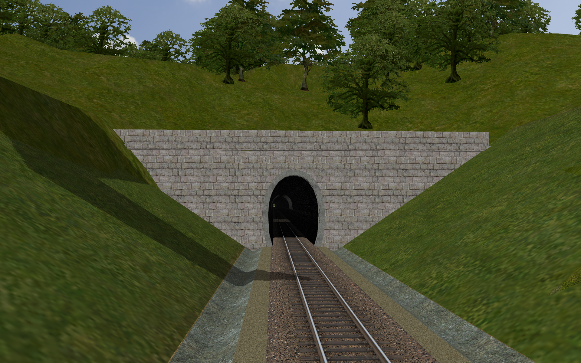
In the other picture, there is a notch made with a modeling program with trenches on both edges. Unfortunately, this solution also has a serious drawback. All such items must be made individually and made to measure. The upper edge of the notch should roughly match the terrain points.
Sincerely, Laci 1959
https://kephost.net/p/2022/37/4476_4eb24a7fb378.png
https://kephost.net/p/2022/24/5500_f442776948cb.png
My problem with this is that TSRE does not know the marking and sizing system of track designers. The slope is given in a ratio pair. 1:1.5 means that one meter of height corresponds to one and a half meters of horizontal distance. This is one of the extreme values as long as it can be used. The other extreme value is 1:1. They don't make it steeper because of the risk of falling. German railways also use these values.
By the way, this is also used for the slope of the railway track, where the horizontal distance is fixed at 1000 meters. This is how the slope expressed in thousandths comes out.
Unfortunately, this cannot be used this way. MSTS was better because the angle of the slope had to be specified. That was easy to determine by editing.
One of the pictures shows a part of the educational material used for the training of railway track designers. Next to the substructure, there is also a drainage ditch on both sides.
In the other picture, there is a notch made with a modeling program with trenches on both edges. Unfortunately, this solution also has a serious drawback. All such items must be made individually and made to measure. The upper edge of the notch should roughly match the terrain points.
Sincerely, Laci 1959
https://kephost.net/p/2022/37/4476_4eb24a7fb378.png
https://kephost.net/p/2022/24/5500_f442776948cb.png
Page 1 of 1