 Log In
 Register Now!
 Help
Help

I've been thinking about ways to improve the performance of Open Rails recently. Besides optimizing the graphics engine, the most obvious way is for route designers to use LODs appropriate for the size of the object. For example, no sense drawing a bush if it's 5,000 meters away. I'm aware that OR as it exists now several options which let the end user choose a balance between performance and appearance appropriate for their hardware. We can further improve on that by using LODs. I'm aware this topic has already been discussed extensively. Sure, the route builder can use LODs to match the size of the object. The end user can even do this if they're willing to uncompress thousands of object files, figure out the size of each, adjust the LODs by hand, and recompress them. This is obviously too tedious for most people. Therefore, I suggest developing a tool to do this. The tool would do the following:
1) Copy all the shapes in a given folder, such as USA1/Shapes, into a temporary folder.
2) Uncompress all the shapes.
3) Calculate the size of each shape, and adjust the LODs. The end user can choose the number of pixels under which an object wouldn't be drawn, and the tool would calculate the LOD.
4) Recompress the shapes.
5) Save all the original shapes in another folder, perhaps USA1/Shapes/original going by the example above.
5) Copy the new shape files into the original folder, overwriting the old ones.
6) Delete the temporary folder.
A nice optional feature if it doesn't entail too much extra work would be to put all the original shapes into a .zip folder instead of saving them individually. This would save potentially having hundreds of thousands of extra files.
Any thoughts? Anyone here able and willing to tackle a project like this? I obviously don't have the programming skills to tackle something like this or I would attempt it myself.
Tool to automatically adjust LODs based on object size
Rate Topic:

#1

- Fireman
-

- Group: Posts: Active Member
- Posts: 185
- Joined: 13-December 09
- Gender:Male
-
Country:

Posted 25 June 2018 - 10:03 AM
#2
- Owner Emeritus and Admin
-

- Group: ET Admin Group
- Posts: 15,661
- Joined: 11-January 04
- Gender:Male
- Location:United States
- Simulator:Open Rails
-
Country:
Posted 25 June 2018 - 11:16 AM
Perhaps a better choice would be for OR to simply evaluate the dimensions of the bounding box and cull the entire shape when it meets certain criteria further than 2000m.
A different solution (one I prefer) could be the addition of a MaxDisplay() in the .sd file. Let OR assume the value is 2000m if that parameter is missing; It it is present use whatever distance it specifies, short or far.
Both of these are likely far easier to implement.
A different solution (one I prefer) could be the addition of a MaxDisplay() in the .sd file. Let OR assume the value is 2000m if that parameter is missing; It it is present use whatever distance it specifies, short or far.
Both of these are likely far easier to implement.
#3
- Fireman
-
- Group: Posts: Active Member
- Posts: 185
- Joined: 13-December 09
- Gender:Male
-
Country:
Posted 25 June 2018 - 11:57 AM
 Genma Saotome, on 25 June 2018 - 11:16 AM, said:
Perhaps a better choice would be for OR to simply evaluate the dimensions of the bounding box and cull the entire shape when it meets certain criteria further than 2000m.
A different solution (one I prefer) could be the addition of a MaxDisplay() in the .sd file. Let OR assume the value is 2000m if that parameter is missing; It it is present use whatever distance it specifies, short or far.
Both of these are likely far easier to implement.
A different solution (one I prefer) could be the addition of a MaxDisplay() in the .sd file. Let OR assume the value is 2000m if that parameter is missing; It it is present use whatever distance it specifies, short or far.
Both of these are likely far easier to implement.
Those are all great ideas. Yes, having OR evaluate the bounding box is a pretty good idea. I wonder if this would be all that expensive from a computational point of view (as the CPU would be doing it as opposed to the GPU)?
#4
- Superintendant
-

- Group: Posts: Elite Member
- Posts: 1,061
- Joined: 18-July 17
- Gender:Male
- Location:Hastings, MN, US
- Simulator:ORTS
-
Country:
Posted 25 June 2018 - 06:53 PM
ModelConverterX actually has an auto-LOD feature that is somewhat similar to this for MSFS models - it doesn't batch process, but it uses an algorithm to create reduced-triangle LODs that actually works pretty well. I ought to ask Arno if there's any way he'd be willing to adapt this to something that can work for MSTS/OR models.
#5
- Owner Emeritus and Admin
-
- Group: ET Admin Group
- Posts: 15,661
- Joined: 11-January 04
- Gender:Male
- Location:United States
- Simulator:Open Rails
-
Country:
Posted 25 June 2018 - 09:24 PM
jtr1962, on 25 June 2018 - 11:57 AM, said:
Those are all great ideas. Yes, having OR evaluate the bounding box is a pretty good idea. I wonder if this would be all that expensive from a computational point of view (as the CPU would be doing it as opposed to the GPU)?
It could be done in the loader thread. The Render/game loop is already over burdened.
The problem w/ trying to apply a LOD to individual faces is what do you do when the small face is actually an integral part of a larger surface? The parallel faces that make up a pipe are individually narrow but in total represent a much larger shape. Anything that represents a curved surface would be improperly LOD'd.
#6
- Superintendant
-
- Group: Posts: Elite Member
- Posts: 1,061
- Joined: 18-July 17
- Gender:Male
- Location:Hastings, MN, US
- Simulator:ORTS
-
Country:
Posted 26 June 2018 - 12:27 AM
Genma Saotome, on 25 June 2018 - 09:24 PM, said:
It could be done in the loader thread. The Render/game loop is already over burdened.
What are you t...a...l...k...i...n...g about? The load seems p..u...r...e..l...y... nominal to m...e...! So long as you look a...w...a...y... for five seconds every m...i...n...u...t...e... or so!
;)
The way that you create your LODs has a lot to do with the end result. You can avoid a lot of the problems with curved surfaces with a little planning and careful vertex welding, but it does take some work, and you have to set the distances so that the changes occur on a model that is small enough on-screen for the reduction to be more or less invisible. A secondary problem is that OR follows the MSTS convention of relying on distance instead of size on screen (which is what MSFS does). LODs in MSTS/OR only really work when the zoom is within a nominal amount. Anything beyond that, and you'll see the change. It's a balancing act.
#7
- Fireman
-
- Group: Posts: Active Member
- Posts: 185
- Joined: 13-December 09
- Gender:Male
-
Country:
Posted 26 June 2018 - 07:16 AM
ErickC, on 25 June 2018 - 06:53 PM, said:
ModelConverterX actually has an auto-LOD feature that is somewhat similar to this for MSFS models - it doesn't batch process, but it uses an algorithm to create reduced-triangle LODs that actually works pretty well. I ought to ask Arno if there's any way he'd be willing to adapt this to something that can work for MSTS/OR models.
From my research into the issue the problem is more one of draw calls than drawing triangles. Modern GPUs can draw billions of triangles per second. Because of this, I'm not sure it makes sense to have multiple LODs for an object (except maybe on very complex objects which appear multiple times in a scene, such as rolling stock). Rather, just have one LOD which basically decides whether or not the object is drawn at all. Of course, we could probably do this in the .sd file just by looking at the size of the bounding box. I also like the idea of a MaxDisplay() line in the .sd file, although that runs into the same issue as adjusting the LODs in the shape file, namely that the end user has to go through thousands of files, unless a utility could be made to automatically add the MaxDisplay() line.
#8
- Owner Emeritus and Admin
-
- Group: ET Admin Group
- Posts: 15,661
- Joined: 11-January 04
- Gender:Male
- Location:United States
- Simulator:Open Rails
-
Country:
Posted 26 June 2018 - 08:09 AM
@Erick The loader thread as I see it on my machine is not much of an issue. Am I to understand that what you see is a big problem? If it is a problem it seems to me that simple solution would be a second loader thread... one for the world file tasks and the other for dealing with reading \tiles. The later could be enhanced to determine which patches share the tertex and microtex files and by communicating that data to the render thread the software could require far fewer drawcalls (right now it does 1 per patch, 256 per tile). In some cases that could drop to one or two. I think that would help everything.
WRT where does the shape become invisible... yeah, it largely depends on screen resolution. IIRC I calculated 1 inch of face surface becomes 1 pixel at 125m when viewed at 1920x1200 (or 1080) resolution. From that it becomes a judgement issue of whether you set the LOD for any face based on that... or some lesser distance. For example, I'll do a much shorter LOD when the face is at a peculiar angle not well suited for normal viewing and/or the object itself is placed well into the background off to the side where the winking might not be noticed. But up close to where the camera -- and your eye -- normally goes? I'll follow that 1" to 125m rule.
WRT where does the shape become invisible... yeah, it largely depends on screen resolution. IIRC I calculated 1 inch of face surface becomes 1 pixel at 125m when viewed at 1920x1200 (or 1080) resolution. From that it becomes a judgement issue of whether you set the LOD for any face based on that... or some lesser distance. For example, I'll do a much shorter LOD when the face is at a peculiar angle not well suited for normal viewing and/or the object itself is placed well into the background off to the side where the winking might not be noticed. But up close to where the camera -- and your eye -- normally goes? I'll follow that 1" to 125m rule.
#9

- Open Rails Developer
-
- Group: Posts: Elite Member
- Posts: 5,514
- Joined: 30-June 10
- Gender:Not Telling
- Simulator:Open Rails
-
Country:

Posted 26 June 2018 - 10:52 AM
jtr1962, on 25 June 2018 - 10:03 AM, said:
Any thoughts? Anyone here able and willing to tackle a project like this? I obviously don't have the programming skills to tackle something like this or I would attempt it myself.
If you just want to scale the LODs such that the object disappears when smaller than N pixels on your screen, we can pretty easily do that inside OR I believe because:
- We know the screen resolution being used
- We know the size of the object (bounding box, view sphere, and actual graphical data)
- You could set the smallest size you care about (N pixels)
- Shapes include a distance with every LOD including the last (which is when the object disappears normally), so we'd scale them all so the last one matches the calculated distance
One wrinkle is that the last LOD may well be set to 2000 in many objects purely because of MSTS, not because it was the right distance relative to the others; for those cases, we could take Dave's suggestion of MaxDisplay() in the .sd file and have it override that final LOD distance before Open Rails starts scaling it all (this means that it is just substituting for editing the shape file itself, not providing any extra functionality).
All this would be done in the loader and sounds like it'd be a trivial amount of work for the CPU, as we're just doing some very basic maths and adjusting the LODs. Once adjusted, the LODs would be static and control the rendering as normal.
#10
- Fireman
-
- Group: Posts: Active Member
- Posts: 185
- Joined: 13-December 09
- Gender:Male
-
Country:
Posted 26 June 2018 - 11:18 AM
James Ross, on 26 June 2018 - 10:52 AM, said:
If you just want to scale the LODs such that the object disappears when smaller than N pixels on your screen, we can pretty easily do that inside OR I believe because:
One wrinkle is that the last LOD may well be set to 2000 in many objects purely because of MSTS, not because it was the right distance relative to the others; for those cases, we could take Dave's suggestion of MaxDisplay() in the .sd file and have it override that final LOD distance before Open Rails starts scaling it all (this means that it is just substituting for editing the shape file itself, not providing any extra functionality).
All this would be done in the loader and sounds like it'd be a trivial amount of work for the CPU, as we're just doing some very basic maths and adjusting the LODs. Once adjusted, the LODs would be static and control the rendering as normal.
- We know the screen resolution being used
- We know the size of the object (bounding box, view sphere, and actual graphical data)
- You could set the smallest size you care about (N pixels)
- Shapes include a distance with every LOD including the last (which is when the object disappears normally), so we'd scale them all so the last one matches the calculated distance
One wrinkle is that the last LOD may well be set to 2000 in many objects purely because of MSTS, not because it was the right distance relative to the others; for those cases, we could take Dave's suggestion of MaxDisplay() in the .sd file and have it override that final LOD distance before Open Rails starts scaling it all (this means that it is just substituting for editing the shape file itself, not providing any extra functionality).
All this would be done in the loader and sounds like it'd be a trivial amount of work for the CPU, as we're just doing some very basic maths and adjusting the LODs. Once adjusted, the LODs would be static and control the rendering as normal.
Thanks for the explanation. I'm leaning more and more in the direction of having OR do this, rather than altering a bunch of files. It does sound like a trivial amount of work for the CPU.
#11
- Superintendant
-
- Group: Posts: Elite Member
- Posts: 1,061
- Joined: 18-July 17
- Gender:Male
- Location:Hastings, MN, US
- Simulator:ORTS
-
Country:
Posted 26 June 2018 - 02:26 PM
jtr1962, on 26 June 2018 - 07:16 AM, said:
From my research into the issue the problem is more one of draw calls than drawing triangles. Modern GPUs can draw billions of triangles per second. Because of this, I'm not sure it makes sense to have multiple LODs for an object (except maybe on very complex objects which appear multiple times in a scene, such as rolling stock).
That's a common misunderstanding. Triangles don't directly impact performance, but they still impact it indirectly. More accurately, triangles don't matter, but verts do, and reducing triangles reduces vertices - often by a factor of two, because UV coordinates also impact that number. It's just easier to say "triangles" because few people understand how vertices are accounted for (hard edges, bad mapping, inefficient model building).
Bones also can create significant performance problems when used irresponsibly. It just ain't as simple as drawcall counts.
There's some better information here. In particular (from a linked post in the article):
Quote
As next gen technology came online, people started repeating this mantra: "Polygons don't matter anymore." For the longest time (okay, about a week) I was stuck thinking, "Awesome, we can throw any amount of geometry at the new cards and they'll just handle it. Sweet!" The part that the infamous "they" left off of that Mantra was: "...vertices do!"
So polygons don't matter anymore. That is absolutely true. However vertices do. They matter absolutely. Here's a handy little excercise to see what I mean by this. Open up 3ds Max or Gmax (or follow along in your mind). Create a box. Convert it to an editable mesh and apply a UVW Unwrap modifier. Collapse it back to a mesh and type in "getNumTverts $" in the Max Script listener window. In the listener output window, you should see the number 8 appear. That means it has 8 texture vertices. That makes sense, 8 physical vertices and 8 texture vertices, right? Now apply a UVW Map modifier to the box and choose "face" as the mapping type. Collapse it back to a mesh and type in "getNumTverts $" in the Max Script listener. You should now see the number 36 appear in the listener output. Huh? 36 texture vertices on a simple box? This is because any texture vertex that is not welded gets duplicated. That happens in the game as well. It also happens for shading groups. We do do some optimization and welding when we convert the geometry to a model, however any hard edge in the UVW Mapping will always cause a split in vertices.
So what this means is that even though your polygon count may be low, your vertex count may be sky high. Like I said, we do optimize pretty heavily on export, but we can't catch every case and if the model is authored poorly from the start (completely unique texture vertices for all the faces for example) you can wind up with four times as many vertices as you intended.
So why does the vertex count matter? Well, because all of the geometry is put onto the graphics card via vertex streams and vertex buffers. A vertex buffer is basically 64k, which translates to ~64,000 vertices stored per buffer. Every buffer is a single draw call. Sometimes we fill the buffer up all the way, sometimes we don't (bad batching). However, let's assume the best case scenario and imagine that we are batching everything perfectly. We create a building that we wan't to appear in a scene 1,000 times. That building has 1000 polygons. Okay, that's a little high, but not bad for a high-detailed model. But due to poor modeling, UVing and smoothing, the building actually has 2400 vertices in it. 64,000 / 2400 = 26 buildings per draw call. 1000 / 26 = 38.4 or 39 draw calls for those buildings. Even though it's a perfect batch and a perfect scenario, we still require 39 draw calls for that single building 1000 times. Let's imagine that the building was well authored and optimized and actually only had 1200 vertices in it (a more reasonable scenario). 64,000 / 1200 = 53 buildings per draw call. 1000 / 53 = 18.8 or 19 draw calls. That's a pretty significant reduction. Especially if you have 200 variations of buildings you want to draw (200 * 39 = 7800 draw calls, 200 * 19 = 3800 draw calls). These are all still excessive numbers, but you get the point (and also can see how creating high-polygon models with bad vertex optimization can kill the framerate quick).
Genma Saotome, on 26 June 2018 - 08:09 AM, said:
@Erick The loader thread as I see it on my machine is not much of an issue. Am I to understand that what you see is a big problem?
Nah, I was making fun of the render process being pegged at basically 100% all the time on my machine... OR goes into slow-motion mode, my wheels slip, and the speedometer goes crazy every 40 seconds or so. ;)
Though, in all seriousness, the poor optimization of most MSTS models is probably a big factor in this.
James Ross, on 26 June 2018 - 10:52 AM, said:
If you just want to scale the LODs such that the object disappears when smaller than N pixels on your screen, we can pretty easily do that inside OR I believe because:
One wrinkle is that the last LOD may well be set to 2000 in many objects purely because of MSTS, not because it was the right distance relative to the others; for those cases, we could take Dave's suggestion of MaxDisplay() in the .sd file and have it override that final LOD distance before Open Rails starts scaling it all (this means that it is just substituting for editing the shape file itself, not providing any extra functionality).
All this would be done in the loader and sounds like it'd be a trivial amount of work for the CPU, as we're just doing some very basic maths and adjusting the LODs. Once adjusted, the LODs would be static and control the rendering as normal.
- We know the screen resolution being used
- We know the size of the object (bounding box, view sphere, and actual graphical data)
- You could set the smallest size you care about (N pixels)
- Shapes include a distance with every LOD including the last (which is when the object disappears normally), so we'd scale them all so the last one matches the calculated distance
One wrinkle is that the last LOD may well be set to 2000 in many objects purely because of MSTS, not because it was the right distance relative to the others; for those cases, we could take Dave's suggestion of MaxDisplay() in the .sd file and have it override that final LOD distance before Open Rails starts scaling it all (this means that it is just substituting for editing the shape file itself, not providing any extra functionality).
All this would be done in the loader and sounds like it'd be a trivial amount of work for the CPU, as we're just doing some very basic maths and adjusting the LODs. Once adjusted, the LODs would be static and control the rendering as normal.
That would be awesome. The MSTS system has always been predicated on a whole lot of assumptions about the player.
jtr1962, on 26 June 2018 - 11:18 AM, said:
Thanks for the explanation. I'm leaning more and more in the direction of having OR do this, rather than altering a bunch of files. It does sound like a trivial amount of work for the CPU.
It's not. What James is talking about is how the sim loads a model's pre-existing LODs, or how it overrides its maximum draw distance when the LOD distance is inappropriate, not how the sim would weld vertices on-the-fly to create LODs where none exist. Since you can't just weld vertices arbitrarily - or the end result will look like garbage - you'd have to use some kind of vertex clustering algorithm like MCX uses if you want to automate the process... and that can take several minutes per LOD depending on the vertex count.
#12
- Owner Emeritus and Admin
-
- Group: ET Admin Group
- Posts: 15,661
- Joined: 11-January 04
- Gender:Male
- Location:United States
- Simulator:Open Rails
-
Country:
Posted 26 June 2018 - 03:37 PM
If your LOD's can cause a texture file to be culled before passing data to the CPU you've done a good thing.
#13
- Superintendant
-
- Group: Posts: Elite Member
- Posts: 1,061
- Joined: 18-July 17
- Gender:Male
- Location:Hastings, MN, US
- Simulator:ORTS
-
Country:
Posted 26 June 2018 - 04:37 PM
Mine don't, but that's because there's nothing to cull when you only use one material for everything. :D ;)
#14
- Owner Emeritus and Admin
-
- Group: ET Admin Group
- Posts: 15,661
- Joined: 11-January 04
- Gender:Male
- Location:United States
- Simulator:Open Rails
-
Country:
Posted 26 June 2018 - 06:33 PM
ErickC, on 26 June 2018 - 04:37 PM, said:
Mine don't, but that's because there's nothing to cull when you only use one material for everything. :D ;)
Fair enough. But I'll wager if you were working on the model that I have in front of me right now, trackside, four buildings, 584 ft long, 80ft high, you'd be using more than one texture.
I do have a couple of questions for you. I read the things on that link you posted and there was something that didn't quite stick between my ears and that's the bit about UV Verticies. Is he recommending the corner of the texture be placed exactly at the corner of the face it is being applied to? What happens when a texture is repeated across a face? Does each repeat create UV Verticies?
#15
- Superintendant
-
- Group: Posts: Elite Member
- Posts: 1,061
- Joined: 18-July 17
- Gender:Male
- Location:Hastings, MN, US
- Simulator:ORTS
-
Country:
Posted 27 June 2018 - 12:10 AM
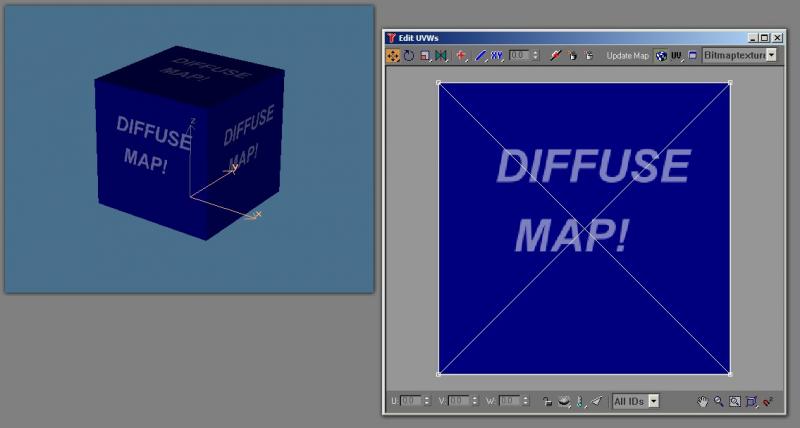
It's easier to demonstrate visually. Let's use my cross-platform friend, the material test cube, which I use whenever I need to test materials or anything else that I don't want a complex model in the way of. Here is how it's mapped - as you can see, all faces share the same UV coordinates:
I can scale these coordinates down, and it looks like this:
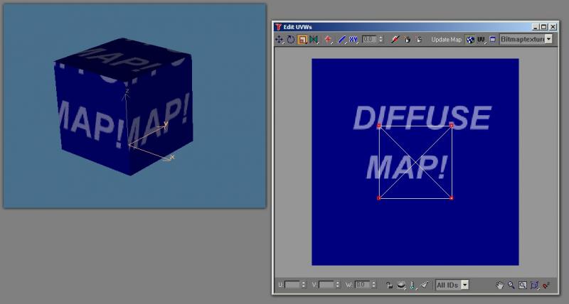
When you tile your textures, you're really just making the area of the coordinates larger than the map itself:
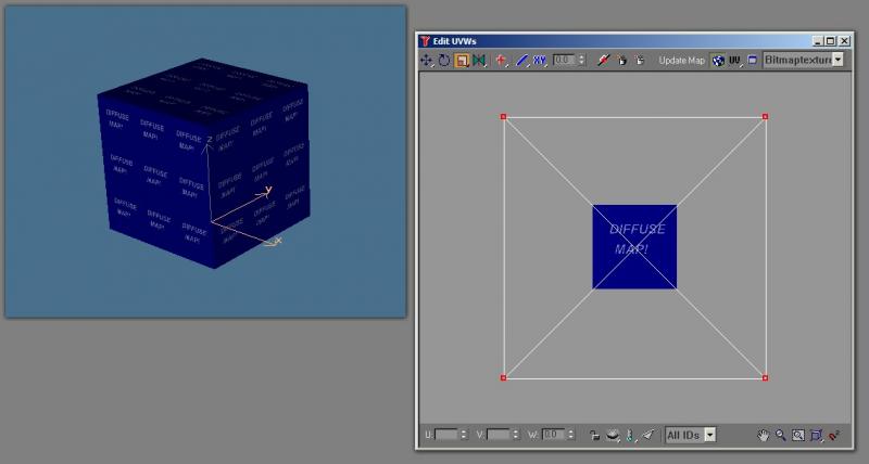
Because some of your coordinates are beyond the boundaries of the map, the map simply repeats itself. Either way, the number of UV coordinates is the same: four.
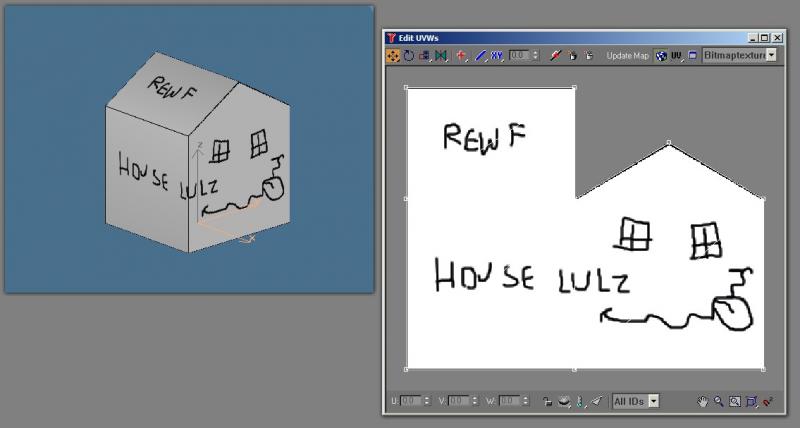
Here, I've constructed a simple house. By my counts, it has 22 vertices. It would have more, but I made a little bet. I've eliminated the hard edge where the roof and sides meet, to eliminate two vertices per side (the modelling program will only list 10 vertices for the geometry, but, in the exported model, a hard edge is created by breaking the vertices along that edge). The bet is that this will be more or less invisible under most conditions when a texture with a crease line is added.
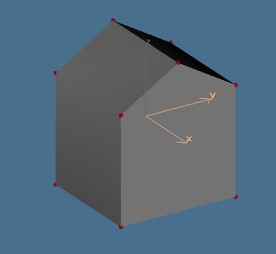
I have created a simple texture for it, and I've mapped it. Notice that I have made the texture as efficient as is possible. I could have made each polygon discrete on the map, but I went with the bare minimum and used the same texture for both "halves" of the house (that is, the front and back are mapped to the same spot, as are the left and right sides). I have also ensured that as many edges as possible share vertices, and, after everything was moved into position, I scaled everything down to a plane from the side, and welded the vertices. This means that the mapping should only add 9 vertices, for a grand total of 31. Typing getNumTverts $ in the MaxScript listener confirms that this model indeed only uses 9 texture vertices.
But I can have the textures tile on this, too, again by scaling the mapping beyond the boundaries of the map area:
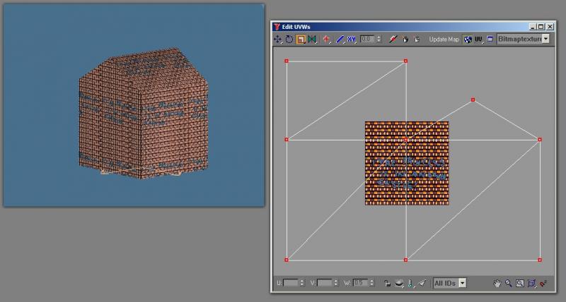
But... the limitation is that you lose a whole lot of control over the roof. The whole texture, obviously, must repeat, and be fairly uniform. This means that the roof ends up looking like it's made of brick. Of course, you can assign a different material to the roof, but that's a drawcall. So it's a balancing act. For large buildings, you probably won't be able to minimize vertices and drawcalls as much as with a simple house if you don't want to use very large textures (which is certainly a viable option today because storage space is cheap and more modern games don't have the memory limitations that older ones do - but the standard version of OR is still limited in that regard by XPs capabilities, as we all know). But buildings large enough to require tiling aren't going to be very common in most areas, so you can probably get away with it without a huge hit so long as the small things are built as efficiently as possible. Even still, with careful mapping and vertex welding, you can eliminate a lot of waste... if your modeling program has the same mapping capabilities as 3DS/GMax. The problem is that few do. I think 3DC does. And this, coupled to a lack of understanding, is one of the big reasons why many MSTS and OR models are so poorly optimized - TSM is certainly a big part of that problem.
I can scale these coordinates down, and it looks like this:
When you tile your textures, you're really just making the area of the coordinates larger than the map itself:
Because some of your coordinates are beyond the boundaries of the map, the map simply repeats itself. Either way, the number of UV coordinates is the same: four.
Here, I've constructed a simple house. By my counts, it has 22 vertices. It would have more, but I made a little bet. I've eliminated the hard edge where the roof and sides meet, to eliminate two vertices per side (the modelling program will only list 10 vertices for the geometry, but, in the exported model, a hard edge is created by breaking the vertices along that edge). The bet is that this will be more or less invisible under most conditions when a texture with a crease line is added.
I have created a simple texture for it, and I've mapped it. Notice that I have made the texture as efficient as is possible. I could have made each polygon discrete on the map, but I went with the bare minimum and used the same texture for both "halves" of the house (that is, the front and back are mapped to the same spot, as are the left and right sides). I have also ensured that as many edges as possible share vertices, and, after everything was moved into position, I scaled everything down to a plane from the side, and welded the vertices. This means that the mapping should only add 9 vertices, for a grand total of 31. Typing getNumTverts $ in the MaxScript listener confirms that this model indeed only uses 9 texture vertices.
But I can have the textures tile on this, too, again by scaling the mapping beyond the boundaries of the map area:
But... the limitation is that you lose a whole lot of control over the roof. The whole texture, obviously, must repeat, and be fairly uniform. This means that the roof ends up looking like it's made of brick. Of course, you can assign a different material to the roof, but that's a drawcall. So it's a balancing act. For large buildings, you probably won't be able to minimize vertices and drawcalls as much as with a simple house if you don't want to use very large textures (which is certainly a viable option today because storage space is cheap and more modern games don't have the memory limitations that older ones do - but the standard version of OR is still limited in that regard by XPs capabilities, as we all know). But buildings large enough to require tiling aren't going to be very common in most areas, so you can probably get away with it without a huge hit so long as the small things are built as efficiently as possible. Even still, with careful mapping and vertex welding, you can eliminate a lot of waste... if your modeling program has the same mapping capabilities as 3DS/GMax. The problem is that few do. I think 3DC does. And this, coupled to a lack of understanding, is one of the big reasons why many MSTS and OR models are so poorly optimized - TSM is certainly a big part of that problem.