Log In
 Register Now!
 Help
Help


 jtr1962, on 26 June 2018 - 07:16 AM, said:
From my research into the issue the problem is more one of draw calls than drawing triangles. Modern GPUs can draw billions of triangles per second. Because of this, I'm not sure it makes sense to have multiple LODs for an object (except maybe on very complex objects which appear multiple times in a scene, such as rolling stock).
That's a common misunderstanding. Triangles don't directly impact performance, but they still impact it indirectly. More accurately, triangles don't matter, but verts do, and reducing triangles reduces vertices - often by a factor of two, because UV coordinates also impact that number. It's just easier to say "triangles" because few people understand how vertices are accounted for (hard edges, bad mapping, inefficient model building).
Bones also can create significant performance problems when used irresponsibly. It just ain't as simple as drawcall counts.
There's some better information here. In particular (from a linked post in the article):
Quote
As next gen technology came online, people started repeating this mantra: "Polygons don't matter anymore." For the longest time (okay, about a week) I was stuck thinking, "Awesome, we can throw any amount of geometry at the new cards and they'll just handle it. Sweet!" The part that the infamous "they" left off of that Mantra was: "...vertices do!"
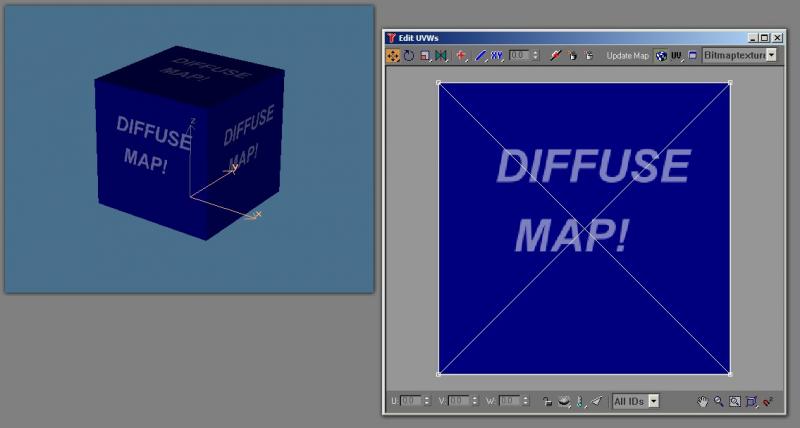
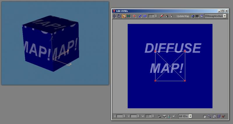
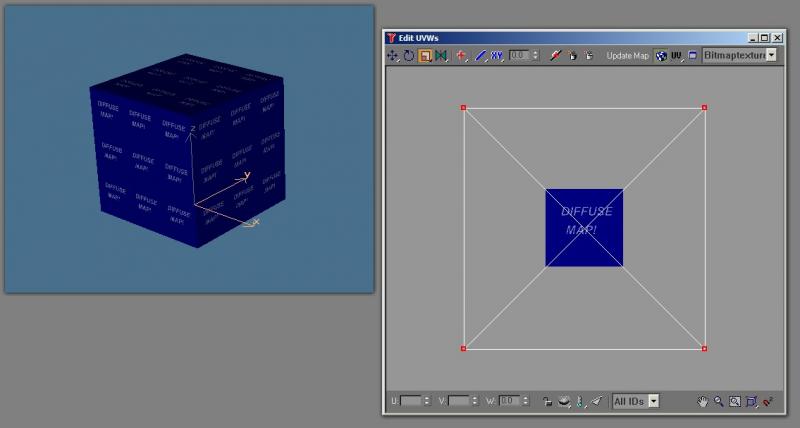
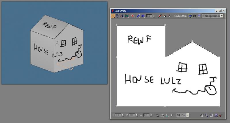
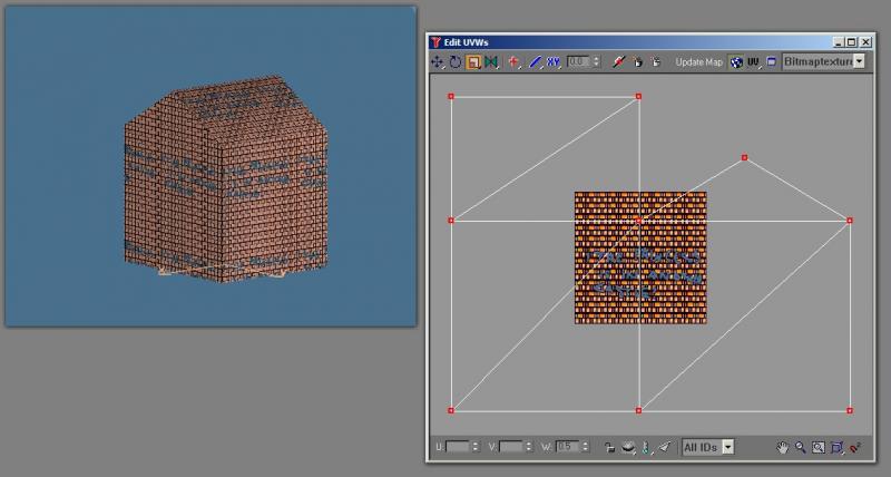
So polygons don't matter anymore. That is absolutely true. However vertices do. They matter absolutely. Here's a handy little excercise to see what I mean by this. Open up 3ds Max or Gmax (or follow along in your mind). Create a box. Convert it to an editable mesh and apply a UVW Unwrap modifier. Collapse it back to a mesh and type in "getNumTverts $" in the Max Script listener window. In the listener output window, you should see the number 8 appear. That means it has 8 texture vertices. That makes sense, 8 physical vertices and 8 texture vertices, right? Now apply a UVW Map modifier to the box and choose "face" as the mapping type. Collapse it back to a mesh and type in "getNumTverts $" in the Max Script listener. You should now see the number 36 appear in the listener output. Huh? 36 texture vertices on a simple box? This is because any texture vertex that is not welded gets duplicated. That happens in the game as well. It also happens for shading groups. We do do some optimization and welding when we convert the geometry to a model, however any hard edge in the UVW Mapping will always cause a split in vertices.
So what this means is that even though your polygon count may be low, your vertex count may be sky high. Like I said, we do optimize pretty heavily on export, but we can't catch every case and if the model is authored poorly from the start (completely unique texture vertices for all the faces for example) you can wind up with four times as many vertices as you intended.
So why does the vertex count matter? Well, because all of the geometry is put onto the graphics card via vertex streams and vertex buffers. A vertex buffer is basically 64k, which translates to ~64,000 vertices stored per buffer. Every buffer is a single draw call. Sometimes we fill the buffer up all the way, sometimes we don't (bad batching). However, let's assume the best case scenario and imagine that we are batching everything perfectly. We create a building that we wan't to appear in a scene 1,000 times. That building has 1000 polygons. Okay, that's a little high, but not bad for a high-detailed model. But due to poor modeling, UVing and smoothing, the building actually has 2400 vertices in it. 64,000 / 2400 = 26 buildings per draw call. 1000 / 26 = 38.4 or 39 draw calls for those buildings. Even though it's a perfect batch and a perfect scenario, we still require 39 draw calls for that single building 1000 times. Let's imagine that the building was well authored and optimized and actually only had 1200 vertices in it (a more reasonable scenario). 64,000 / 1200 = 53 buildings per draw call. 1000 / 53 = 18.8 or 19 draw calls. That's a pretty significant reduction. Especially if you have 200 variations of buildings you want to draw (200 * 39 = 7800 draw calls, 200 * 19 = 3800 draw calls). These are all still excessive numbers, but you get the point (and also can see how creating high-polygon models with bad vertex optimization can kill the framerate quick).
Genma Saotome, on 26 June 2018 - 08:09 AM, said:
@Erick The loader thread as I see it on my machine is not much of an issue. Am I to understand that what you see is a big problem?
Nah, I was making fun of the render process being pegged at basically 100% all the time on my machine... OR goes into slow-motion mode, my wheels slip, and the speedometer goes crazy every 40 seconds or so. ;)
Though, in all seriousness, the poor optimization of most MSTS models is probably a big factor in this.
James Ross, on 26 June 2018 - 10:52 AM, said:
If you just want to scale the LODs such that the object disappears when smaller than N pixels on your screen, we can pretty easily do that inside OR I believe because:
One wrinkle is that the last LOD may well be set to 2000 in many objects purely because of MSTS, not because it was the right distance relative to the others; for those cases, we could take Dave's suggestion of MaxDisplay() in the .sd file and have it override that final LOD distance before Open Rails starts scaling it all (this means that it is just substituting for editing the shape file itself, not providing any extra functionality).
All this would be done in the loader and sounds like it'd be a trivial amount of work for the CPU, as we're just doing some very basic maths and adjusting the LODs. Once adjusted, the LODs would be static and control the rendering as normal.
- We know the screen resolution being used
- We know the size of the object (bounding box, view sphere, and actual graphical data)
- You could set the smallest size you care about (N pixels)
- Shapes include a distance with every LOD including the last (which is when the object disappears normally), so we'd scale them all so the last one matches the calculated distance
One wrinkle is that the last LOD may well be set to 2000 in many objects purely because of MSTS, not because it was the right distance relative to the others; for those cases, we could take Dave's suggestion of MaxDisplay() in the .sd file and have it override that final LOD distance before Open Rails starts scaling it all (this means that it is just substituting for editing the shape file itself, not providing any extra functionality).
All this would be done in the loader and sounds like it'd be a trivial amount of work for the CPU, as we're just doing some very basic maths and adjusting the LODs. Once adjusted, the LODs would be static and control the rendering as normal.
That would be awesome. The MSTS system has always been predicated on a whole lot of assumptions about the player.
jtr1962, on 26 June 2018 - 11:18 AM, said:
Thanks for the explanation. I'm leaning more and more in the direction of having OR do this, rather than altering a bunch of files. It does sound like a trivial amount of work for the CPU.
It's not. What James is talking about is how the sim loads a model's pre-existing LODs, or how it overrides its maximum draw distance when the LOD distance is inappropriate, not how the sim would weld vertices on-the-fly to create LODs where none exist. Since you can't just weld vertices arbitrarily - or the end result will look like garbage - you'd have to use some kind of vertex clustering algorithm like MCX uses if you want to automate the process... and that can take several minutes per LOD depending on the vertex count.