Log In
 Register Now!
 Help
Help

Hi,
The controls for 3d cabs are set up a little bit differently than 2d cabs. There is a combination between the entries in the .eng file and the .cvf file, and the naming of components in the .s file too. I would be help you out by taking a look at these files, if you are able to send the model to me. my email is mrmosky@yahoo.co.uk
For the analogue needles, the animation procedure in TSM is very important. If you want the gauge tilted at an angle of 30 degrees, for instance, then you need to model the non animated parts of the gauge at this angle. That would be the dial face and housing, instrument glass. The animated needle part is not tilted, however, in the modelling. The tilting is part of the animation. So what I do is to place the needle vertically, with it's pivot point at the correct position in the gauge. Then in the animation, each animation step has a fixed rotation of 30 degrees in x axis, and also an incremental step of say 30 degrees in the z axis. For 8 animation steps, that would give a needle rotation of 270 degrees. As in this table. Note that negative rotation is clockwise. So it is best to edit the animation directly in the part properties by pressing F2. It will not look correct in TSM, but it works fine when exported to OR.
Step , x , y , z
0 , 30 , 0 , 0
1 , 30 , 0 , -30
2 , 30 , 0 , -60
3 , 30 , 0 , -90
4 , 30 , 0 , -120
5 , 30 , 0 , -150
6 , 30 , 0 , -180
7 , 30 , 0 , -240
8 , 30 , 0 , -270
Geoff
3D Cabs
Rate Topic:

#571

- Engineer
-

- Group: Status: Contributing Member
- Posts: 648
- Joined: 02-October 16
- Gender:Male
- Location:Chasetown
- Simulator:Openrails
-
Country:

Posted 20 March 2020 - 02:59 AM
#572
- Conductor
-

- Group: Status: Active Member
- Posts: 268
- Joined: 15-March 20
- Gender:Male
- Location:Barcelona, Catalunya
- Simulator:Open Rails
-
Country:

Posted 20 March 2020 - 02:57 PM
Hello Geof. Thank you very much for the directions. I will try to understand them well first (English is not my mother tongue), and when I manage to fix some parts following your indications, I will send you the files in case you can see something I missed. I don't know if the textures are necessary, I guess the .eng and cab files are.
Great!
Great!
#573
- Conductor
-
- Group: Status: Active Member
- Posts: 268
- Joined: 15-March 20
- Gender:Male
- Location:Barcelona, Catalunya
- Simulator:Open Rails
-
Country:
Posted 21 March 2020 - 03:56 PM
Hello!
After carefully studying the issue of the tilted needles in the 3d cockpit that Geoff so kindly explained to me, I have managed to make them work almost perfectly, using the old custom of "trial and error", and I am spreading my conclusions here in the hope that they will be useful to more people. This can save you a lot of headaches. Someday we should build a tutorial with all these issues well explained, so that we don't have to waste so much time building a 3d cockpit, which would encourage many more people to make them.
These are the corrections that I have applied to Geoff's post list, and that I have been able to verify that they work well. Indeed, the plane containing the graph with the needle is built vertically, with the point pointing upwards. Then we have to place the pivot point of the part where we want the rotation to take place on the Z axis.
After the number of frames, the first column refers to the inclination of the needle on the X axis. This varies according to the inclination of the instrument/panel where we want to place it (in this case, 23.5º). The second column is the rotation in the Y plane (in this case none, but I have another needle in the cabin that is on a plane with inclination also on that axis) and the third column is the rotation of the needle in the Z axis. The extremes can vary depending on the instrument. Theoretically the movement should be the same throughout the rotation, but for some mysterious reason, when the needle moves pointing in the upper zone, it suffers from a certain acceleration that I have not yet been able to resolve (for 8 frames):
As you can see, it is necessary to use positive numbers at the beginning, if the rotation movement is from left to right, and vice versa if the rotation is from right to left.
I don't think I'm leaving anything out. I hope that this clears up the issue completely. Thanks to Geoff again, who gave me the keys to understanding this. I still have a lot of things to understand, so you'll see me often in the thread. Cheers!
After carefully studying the issue of the tilted needles in the 3d cockpit that Geoff so kindly explained to me, I have managed to make them work almost perfectly, using the old custom of "trial and error", and I am spreading my conclusions here in the hope that they will be useful to more people. This can save you a lot of headaches. Someday we should build a tutorial with all these issues well explained, so that we don't have to waste so much time building a 3d cockpit, which would encourage many more people to make them.
These are the corrections that I have applied to Geoff's post list, and that I have been able to verify that they work well. Indeed, the plane containing the graph with the needle is built vertically, with the point pointing upwards. Then we have to place the pivot point of the part where we want the rotation to take place on the Z axis.
After the number of frames, the first column refers to the inclination of the needle on the X axis. This varies according to the inclination of the instrument/panel where we want to place it (in this case, 23.5º). The second column is the rotation in the Y plane (in this case none, but I have another needle in the cabin that is on a plane with inclination also on that axis) and the third column is the rotation of the needle in the Z axis. The extremes can vary depending on the instrument. Theoretically the movement should be the same throughout the rotation, but for some mysterious reason, when the needle moves pointing in the upper zone, it suffers from a certain acceleration that I have not yet been able to resolve (for 8 frames):
0;23.5;0;135.0;
1;23.5;0;104.875;
2;23.5;0;74.75;
3;23.5;0;44.6250;
4;23.5;0;-14.5;
5;23.5;0;-44.6250;
6;23.5;0;-74.75;
7;23.5;0;-104.875;
8;23.5;0;-135.0;
As you can see, it is necessary to use positive numbers at the beginning, if the rotation movement is from left to right, and vice versa if the rotation is from right to left.
I don't think I'm leaving anything out. I hope that this clears up the issue completely. Thanks to Geoff again, who gave me the keys to understanding this. I still have a lot of things to understand, so you'll see me often in the thread. Cheers!
#574
- Engineer
-
- Group: Status: Contributing Member
- Posts: 648
- Joined: 02-October 16
- Gender:Male
- Location:Chasetown
- Simulator:Openrails
-
Country:
Posted 22 March 2020 - 02:17 AM
Hi,
That's an interesting observation about the non-linearity. I had not noticed that.
You should also realise that this is a particular issue with TSM. Other modelling tools allow you to rotate about the component's local axis, but in TSM, it is only possible to rotate about the global axis. Blender allows local axis rotation, according to Hamza.
Still, once you understand how to handle this in TSM, it is not a problem.
Cheers,
Geoff
#575
- Conductor
-
- Group: Status: Active Member
- Posts: 268
- Joined: 15-March 20
- Gender:Male
- Location:Barcelona, Catalunya
- Simulator:Open Rails
-
Country:
Posted 27 March 2020 - 02:50 AM
Hi!
Thanks again for the tips.
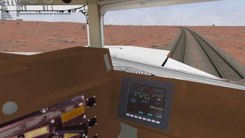
Another problem I can't solve is the tilt of the digital displays. The panel of my locomotive is tilted, I have tried everything but I can't find the way. Could someone help me? Thank you very much!
Thanks again for the tips.
Another problem I can't solve is the tilt of the digital displays. The panel of my locomotive is tilted, I have tried everything but I can't find the way. Could someone help me? Thank you very much!
#576
- Engineer
-
- Group: Status: Contributing Member
- Posts: 606
- Joined: 01-March 15
- Gender:Male
- Simulator:Open Rails
-
Country:

Posted 27 March 2020 - 03:12 AM
Quote
. Blender allows local axis rotation, according to Hamza.
Yup ... :good2:
Quote
Another problem I can't solve is the tilt of the digital displays. The panel of my locomotive is tilted, I have tried everything but I can't find the way. Could someone help me? Thank you very much!
You have to rotate the origin of the plane to point in same direction as the display ..:)
#577
- Conductor
-
- Group: Status: Active Member
- Posts: 268
- Joined: 15-March 20
- Gender:Male
- Location:Barcelona, Catalunya
- Simulator:Open Rails
-
Country:
Posted 27 March 2020 - 04:25 AM
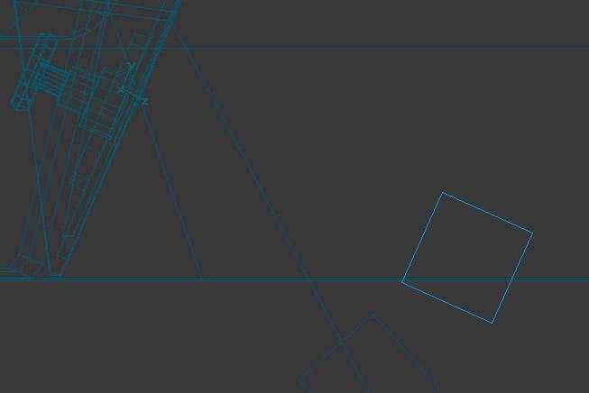
Yes Hamza97, thanks, it's one of the things I've tried, but the numbers still appear totally vertical:
Attached thumbnail(s)
#578
- Conductor
-
- Group: Status: Active Member
- Posts: 268
- Joined: 15-March 20
- Gender:Male
- Location:Barcelona, Catalunya
- Simulator:Open Rails
-
Country:
Posted 29 March 2020 - 05:53 AM
Hello!
I can't fix this. I've looked everywhere but can't find any information. It's not the same as the animations of the needles, I have only managed to make the panels appear by inserting a cube, not a plane, but tilting it is impossible for me. No one knows anything that can explain it to me? Are there any booths with digital tilt panels working?
Thank you very much.
#579
- Conductor
-
- Group: Status: Active Member
- Posts: 268
- Joined: 15-March 20
- Gender:Male
- Location:Barcelona, Catalunya
- Simulator:Open Rails
-
Country:
Posted 03 April 2020 - 02:39 PM
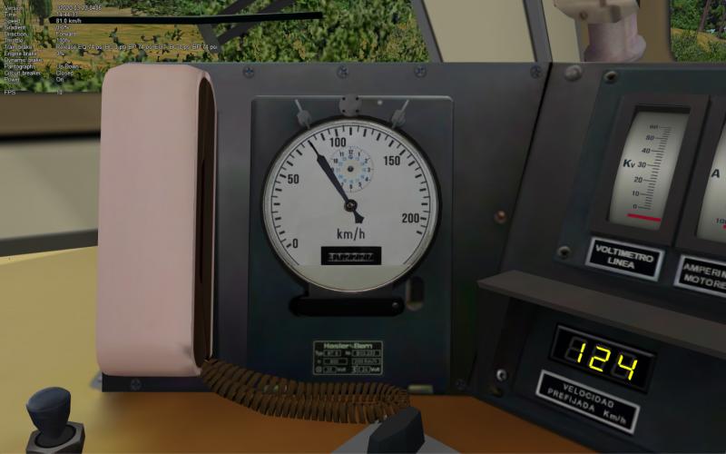
Okay. After a few tests making templates in Photoshop to check each of the angles, I managed to adjust the rotation of the needle to mark the data with much greater precision.
On the screenshot, we can see the settings working. You can check the needle with the real value that OR indicates at the top left:
These are the exact values for the rotation of the needle. Of course, on each instrument it will be slightly different because of the start and end positions, but I think it can help more people, who don't have to break their heads with this:
Two more details. The space to place the analog clock in the cabin, which doesn't seem to be possible for now, or at least I don't find that Open Rails function explained anywhere, and at the bottom right the digital panels that nobody can tell me how they tilt either, and I've tried everything and didn't succeed.
If anyone knows anything, please... speak up!
Greetings!
On the screenshot, we can see the settings working. You can check the needle with the real value that OR indicates at the top left:
These are the exact values for the rotation of the needle. Of course, on each instrument it will be slightly different because of the start and end positions, but I think it can help more people, who don't have to break their heads with this:
0;18.0000;40.0000;135.0000;
1;18.0000;40.0000;100.8750;
2;18.0000;40.0000;68.7500;
3;18.0000;40.0000;34.6250;
4;18.0000;40.0000;0.0000;
5;18.0000;40.0000;-34.4400;
6;18.0000;40.0000;-69.0000;
7;18.0000;40.0000;-103.7000;
Two more details. The space to place the analog clock in the cabin, which doesn't seem to be possible for now, or at least I don't find that Open Rails function explained anywhere, and at the bottom right the digital panels that nobody can tell me how they tilt either, and I've tried everything and didn't succeed.
If anyone knows anything, please... speak up!
Greetings!
#580

- Engineer
-
- Group: Status: Contributing Member
- Posts: 503
- Joined: 28-June 08
- Location:Perth, WA
-
Country:

Posted 03 April 2020 - 10:58 PM
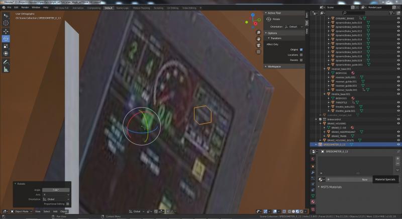
To 'tilt' the digital displays you have to translate and rotate the 'pivot point / origin' for the object, not rotate the object itself. Your screen shot appears to show you have offset the 'pivot point / origin' for the object which is good. However it appears you have then rotated the object around that pivot point / origin, which is not what you need to do.
I don't use TSM so I cant give instructions on how to do it using that program. However, I have built a cab using GMAX and have just tested this on one of the cabs I'm currently building using Blender andc confirmed that it works.
Watch the following video which shows how to rotate a 'pivot point / origin' in Blender. The same concept also works in GMAX but obviously the menu selections and terminology are somewhat different. You may have to ask someone familiar with TSM how to rotate a 'pivot point / origin' if you still cant work it out.
https://www.youtube....h?v=-CiWNcPB1CY
At 1 minute 10 seconds, when you see him rotate the 'pivot point / origin' and then he says “I don't want to rotate that”, that is exactly what you do want to do in order to rotate the 'pivot point / origin' to suit the angle of the display screen.
Below are the steps to add a digital speedometer to a 3D cab. This applies to any digital display, you just change the object name to be any of the other reserved object names for the cab display or controls you are adding at the time.
Please note that the following is also for the benefit of other, possibly brand new cab modellers trying to work this out so excuse any steps that you have already tried or know about.
In the screen shot below, a primitive box object has been created and called 'SPEEDOMETER:0:13'.
It's called SPEEDOMETER because that's the reserved name for a speedometer display, 0 because it's the first (and possibly only) speedometer display referenced in the cab cvf file and 13 because that's the size of the text I want displayed.
The 'SPEEDOMETER:0:13' box has then been scaled down from the 1metre default size to a size approximately the size of the digits you wish display. Note that the size of the 'SPEEDOMETER:0:13' box is unimportant beyond us needing to hide it somewhere in the cab.
Reset the scale transformation for 'SPEEDOMETER:0:13' using CTRL+A. This depends on the modelling program, but if you have weird scaled objects in your exported model but they are OK in your modelling program, its probably because the transformations in your model need to be reset.
The 'SPEEDOMETER:0:13' box is then been moved to the point in the display screen where you want the speed to be displayed.
The 'SPEEDOMETER:0:13' box has then been moved 'forwards' in the Y axis so it is behind the 'screen' and not visible from the 'drivers' normal sitting perspective in the cab.
Then use the instructions in the youtube video above and use the gizmo or 'G' key to move the 'pivot point / origin' in the Y axis 'backwards' so that it is in front of the display screen where the driver would see it. Then use the the gizmo or 'R' key to rotate the 'pivot point / origin', in the 3 axis, to suit the tilt of the display screen. You will note that the 'SPEEDOMETER:0:13' box object has not moved or rotated. You have been making these changes only to the 'pivot point / origin' of the 'SPEEDOMETER:0:13' box object.
Then parent (CTRL+P) the 'SPEEDOMETER:0:13' box to a 'parent' part of the cab.
Apply a texture called SPEED to the 'SPEEDOMETER:0:13' box.
Then export from Blender and ensure you have the 'Retain Name' check box ticked otherwise there is a good chance that the reserved name/s will be mangled.
Then test in game. You will probably have to make adjustments to the 'pivot point / origin' in the 3D modelling program, export and test until it is aligned to your satisfaction. I found with cab rocking and/or super elevation tilt, sometimes the numbers would disappear behind the screen.
Also note that currently, for the digital clock, I have found in the 3D cab that only HH:MM: is displayed. However, in the 2D cab HH:MM:SS is displayed as expected.
Also excuse the state of the cab in the screen shots. This cab is a work in progress and in order to get this out to you in a timely manner you are seeing it warts and all.
Hope this helps.
Cheers,
Marek.