Elvas Tower: Load Meter - Elvas Tower

Jump to content

  • 3 Pages +
  • 1
  • 2
  • 3
  • You cannot start a new topic
  • You cannot reply to this topic

Load Meter Rate Topic: -----

#11 User is offline   Lindsayts 

  • Superintendant
  • Group: Status: Elite Member
  • Posts: 1,849
  • Joined: 25-November 11
  • Gender:Male
  • Country:

Posted 25 July 2013 - 11:32 PM

View PostMatej Pacha, on 25 July 2013 - 09:13 PM, said:

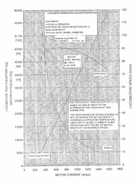
Yes, the theory of electric machines speaks about quadratic relationship between the current and the force/torque but in a very ideal case. If you see the electro-mechanic characteristics of series-wounded DC machine, you'll find the characteristics is nearly linear due to magnetic saturation of the iron core and the self resistance. I've noticed that General Electric locomotives have no field weakening so the force is always given by the same current. European locomotives use this to spread the range of speed so the same force can be produced by at least two different currents. When speaking about AC machines, the current-force dependency is nearly the same because the control technique leads to the force being linear to the current and field.


See my post in the physics section on the emulation of teh current TE curve od a series motor, The data for the emulation came from to sets of graphs, the first being I to TE for an EMD D77 motor, the second another set graphs for a large series wound industrial motor. The two sets of graphs almost mirrored themselves for the current V torque relationship.

Quote


This is interesting. Is this implemented in the DC/DC and AC/DC locos too or just AC/AC? Normally the nominal force/current is somewhere on the half way to the maximal force and the traction motor can be current-overloaded (the diesel engine cannot be power-overloaded).


AC/DC machines, info comes from the maintence manuals for the GE Dash 7 and the EMD GP40. Also the F7 drivers handbook states immediately after starting one can put the throttle up to at least notch 4 without any problems, this implies even the early machines possibly had some kind of current limiting. An interesting note here is it appears nearly all EMD drivers handbooks say this, a number of drivers a spoke to did not realise you could do this until they checked there drivers notes.

The limiting has a slightly different charteristic between the Dash 7 and the GP40, this is probably due to the Dash 7 appears to use electronics for regulation where as the EMD items of this vintage use magnetic amplifiers (a specialised form of transformer controlled by a an auxilary winding passing DC current). The Dash 7's have a specified max I for each notch, once the control gets below the constant power section. the control system will not let the current increase any further. In the EMD the current does increase beyond this point, the altenator though acts is if there is a virtual 0.4 ohm resistor in series with it, Note this is my interpretation based on the loco's altenator output current and voltage graph. I can supply these diagrams if required.

Both the EMD and the GE manuals state one should be able to go straight to Notch 8 on startup without overloading the motors (at least in the short term). EMD machines can almost certainly be set up so the driver can overload the traction motors.

Lindsay

#12 User is offline   Matej Pacha 

  • Engineer
  • Group: Status: Contributing Member
  • Posts: 571
  • Joined: 08-December 10
  • Gender:Male
  • Location:Slovakia
  • Country:

Posted 26 July 2013 - 03:18 AM

Just to support my point: here is the electromechanic characteristics of some GE locomotive. The tractive force is a kind of linear to the current and I believe the linear relation is satisfactory when the traction motors are not simulated.
Attached Image: t_ch_GE.jpg
If we have all the parameters needed, I can easily make a simulation of the traction motors and we'll get correct values. Now we cannot generalize the problem of nonlinearity of the current-force relation. There are locomotives with linear characteristics too.

You might be interrested in this file Attached File  Diesel_DC.xlsx.txt (414.81K)
Number of downloads: 155 (please change the extension to its original xlsx). It is a configurator of the diesel physics based on the common (relative) DC motor characteristics. It is not perfect - it's designed to generate a specific kind of diesel-electric locomotives made in Europe, but you can generate the MaxTractiveForceCurves block for the ENG file...

Matej

#13 User is offline   Lindsayts 

  • Superintendant
  • Group: Status: Elite Member
  • Posts: 1,849
  • Joined: 25-November 11
  • Gender:Male
  • Country:

Posted 27 July 2013 - 12:42 PM

See reply the in the Openrails physics/motor data thread, sorry for the double post on the latter thread Elvas locked up on my browser for some reason.

Lindsay

#14 User is offline   Gehe 

  • Apprentice
  • Group: Status: Active Member
  • Posts: 48
  • Joined: 05-January 14
  • Gender:Male
  • Simulator:MSTS
  • Country:

Posted 01 February 2015 - 10:43 AM

Hi All,


I would like to add a question related to the topic AMMETER.

I experienced a different behaviour of the AMMETER in ORTS compared to MSTS.
In MSTS the maximum deflection of the ammeter can be influenced via the MaxCurrent values for tractive force and dynamic braking.
This means if full scale deflection means 1000A (.cvf) and max current in the .eng is 500A you get 50% deflection.

In ORTS reaching the max tractive force or max braking force means full-scale deflection.
A change of the current values in the .eng does not have any influence on the AMMETER.

Is this behaviour intended?


Regards
Gehe

#15 User is offline   ATW 

  • Engineer
  • Group: Status: Contributing Member
  • Posts: 643
  • Joined: 07-January 13
  • Gender:Male
  • Simulator:MSTS Open Rails
  • Country:

Posted 02 February 2015 - 09:21 PM

I've notice the same thing an other bugs in cab displays having me change an alias my unit's cabs by opening the cvf an adding the unit's maximum load an braking based on eng an saw satisfied results even if it's a pain changing all stock at the times I run them leading.

#16 User is offline   Matej Pacha 

  • Engineer
  • Group: Status: Contributing Member
  • Posts: 571
  • Joined: 08-December 10
  • Gender:Male
  • Location:Slovakia
  • Country:

Posted 04 February 2015 - 08:32 AM

It should be resolved in 2833. The MaxCurrent value is now considered for AMMETER and AMMETER_ABS. Please report issues if any. If LOAD_METER is used with Unit(Amps), MaxForce is taken as a reference.

Matej

#17 User is offline   ATW 

  • Engineer
  • Group: Status: Contributing Member
  • Posts: 643
  • Joined: 07-January 13
  • Gender:Male
  • Simulator:MSTS Open Rails
  • Country:

Posted 04 February 2015 - 08:10 PM

Ammeter works well now matching the eng files MaxCurrent. But can there be a fix for TRACTION_BRAKING to produce a units traction to the rail based on units actual MaxForce an braking? In MSTS this setting plays a good role in telling how much traction force is being put to the rail during movement even slippage where braking force during power braking decreases the power force (Power Traction Force - Braking Force= true traction/braking forces) based on units used in pounds or newtons in the cvf. ORTS Force Information HUD is a good example of this in Brake Force + Axle Out Force in negatives for dynamics, positive for power and adhesion conditions making up total during movement.

#18 User is offline   Gehe 

  • Apprentice
  • Group: Status: Active Member
  • Posts: 48
  • Joined: 05-January 14
  • Gender:Male
  • Simulator:MSTS
  • Country:

Posted 08 February 2015 - 01:25 PM

Hi All,

I checked the behaviour with the version X.2843. With positve forces (tractiive force) it works well now. But with negative Forces (dynamic brake)
the deflection is still not referenced to the .eng Parameter "DynamicBrakesResistorCurrentLimit". The deflection of AMMETER is still related to the relation of actual braking force to max braking force.


Regards

Gehe

#19 User is offline   Matej Pacha 

  • Engineer
  • Group: Status: Contributing Member
  • Posts: 571
  • Joined: 08-December 10
  • Gender:Male
  • Location:Slovakia
  • Country:

Posted 08 February 2015 - 09:12 PM

I was looking for that parameter and couldn't find it in the MSTS examples. I will add it. It would be easier to have a kind of original MSTS documentation if it would exist.

#20 User is offline   hroch 

  • Fireman
  • Group: Status: Active Member
  • Posts: 198
  • Joined: 05-June 14
  • Gender:Male
  • Simulator:MSTS OR
  • Country:

Posted 09 February 2015 - 01:22 AM

Hi
Original MSTS documentation is on disc1 of MSTS installation in folder TECHDOCS.

  • 3 Pages +
  • 1
  • 2
  • 3
  • You cannot start a new topic
  • You cannot reply to this topic

1 User(s) are reading this topic
0 members, 1 guests, 0 anonymous users