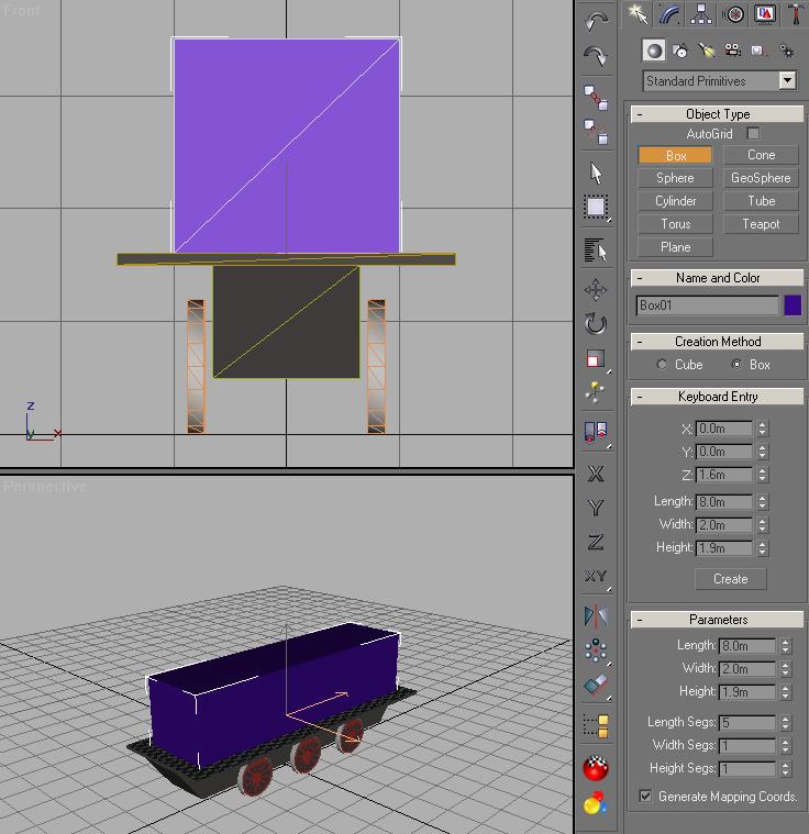
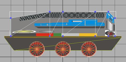
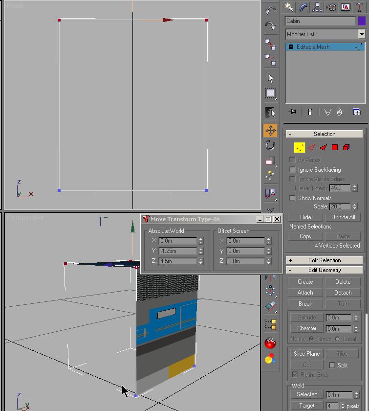
| Using the Front Viewport, click on Vertex
selection mode. Select the outer pair of vertices on either side
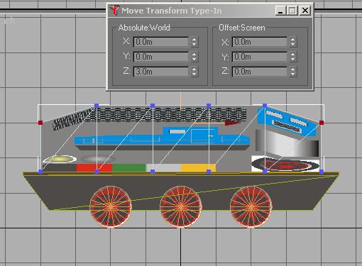
and using the Move Transform-Type-In
dialog, you set the X parameters to 1.25m for one side and
-1.25m for the other. This will stretch the cabin outwards from
center. Then select the top pair of vertices and change their
Z position to 4.5m to raise the cabin height.
Zoom extents to center each viewport. |
 |
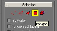
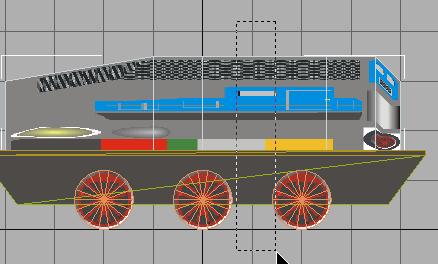
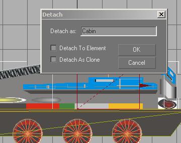
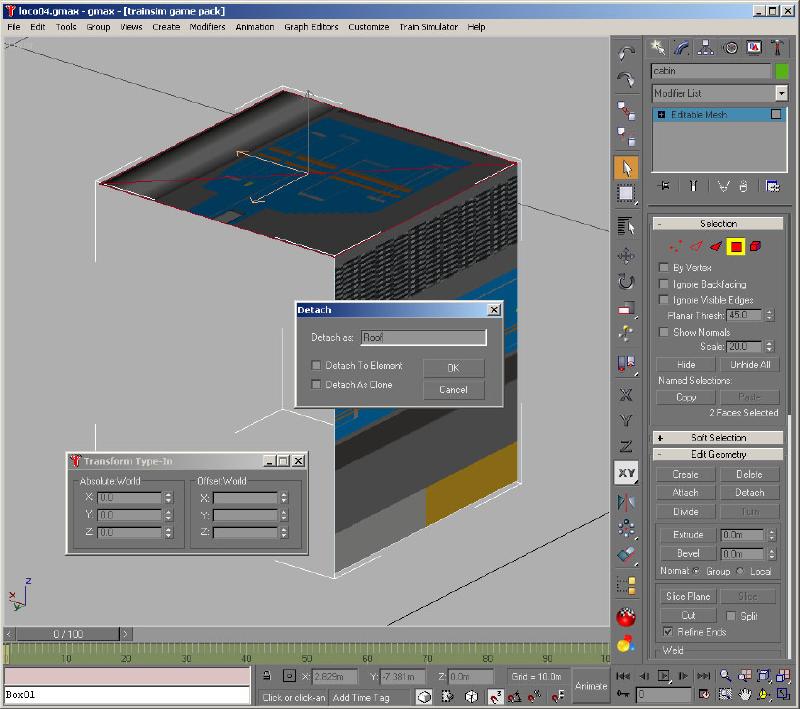
| Now change to the Polygon select mode. Rotate
the view in the Perspective Viewport to give access to
the top of the Cabin. Select the 2 polygons that make up the top
of the cabin and click on Detach. Name the new
detached part Roof. |
 |
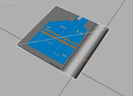
| You are going to shape the roof using an array of 4 equal, identical
sections of the roof. It may be easier to work only with the newly
detached Roof. Activate Polygon
select mode. The Roof polygons should still be
selected. In the Display mode, Hide Unselected
and you should only be left with the Roof showing |
 |
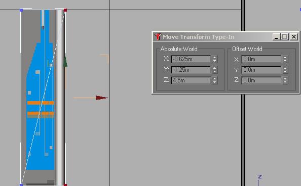
| Moving back to the Modify mode, click on
Vertex select mode. In the Top Viewport, select the
vertices on the right and using the Move Transform-Type-In
dialog, move these vertices to X -.625m. |
 |
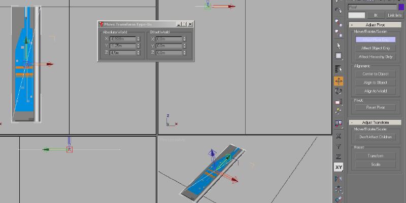
| De-select Vertex selection mode and go into the
Hierarchy mode. Affect Pivot Only,
then Center to Object and Align to World
to set the pivot point as shown below. Close Affect Pivot
Only. |
 |
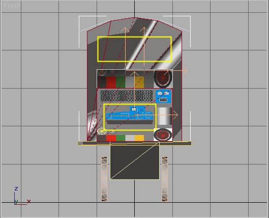
Now you will open the Array Tool.

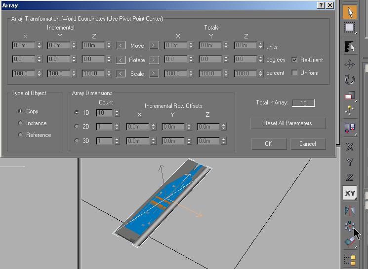
You want to end up with 4 copies of you shape, all lined up to the right
of the existing shape on the X axis. This dialog box is
cluttered and confusing when you first look at it. To get a full
explanation of everything that is shown, look in the GMAX HELP
under Array Dialog,
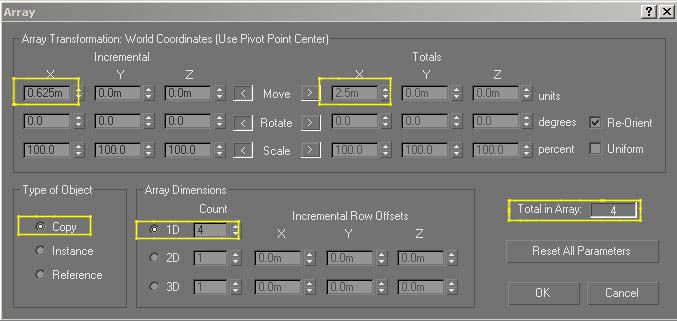
In the image below, the sections that you are concerned with are
highlighted. Each section of the roof is .625m wide
(in the X axis). Our existing shape is sitting on
the negative side of the 0 line of the X axis, so you
want our copies placed in a positive direction towards the 0 or
centerline of the axis. You see the value 0.625m in the
X Incremental settings. If our existing
shape you sitting on the positive side of the X axis,
you
would want our copies placed in a negative direction towards the
centerline and the value in the X Incremental box would read -0.625m.
You have Copy checked and the 1D Count
set to 4. This will give us a total of 4 shapes identical to the
first.
The Totals area shows that the resulting sum of the 4 shapes will extend
for 2.5m along the X axis.
Enter your X Incremental value and the 1D Count
value. The rest of the values are added by the tool.
Click OK.
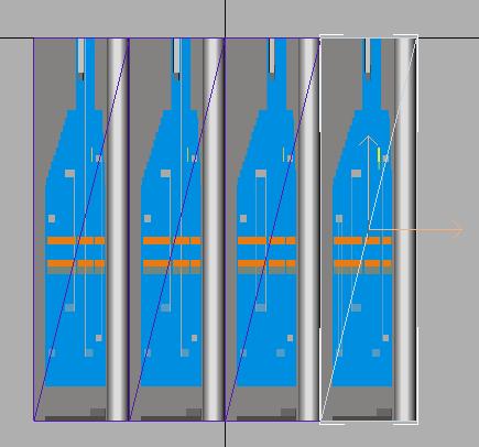
You will see the 4 aligned sections appear in the Top and the
Perspective Viewports. |
 |
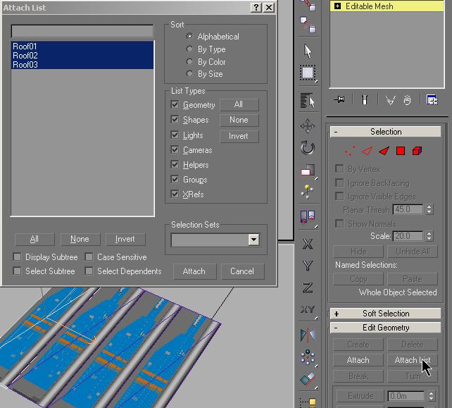
| Now, select the first panel titled Roof. In
the Modify mode, use Attach List to join all the sections together into
one shape called Roof. |
 |
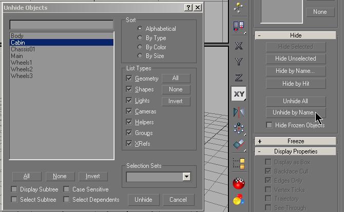
| You now re-attach the Roof to the
Cabin. Select Display mode and click on
Unhide by Name and select the Cabin and
unhide. |
 |
| Go back to the Modify mode and select the
Cabin. Use the Attach List and attach
the Roof to the Cabin. |
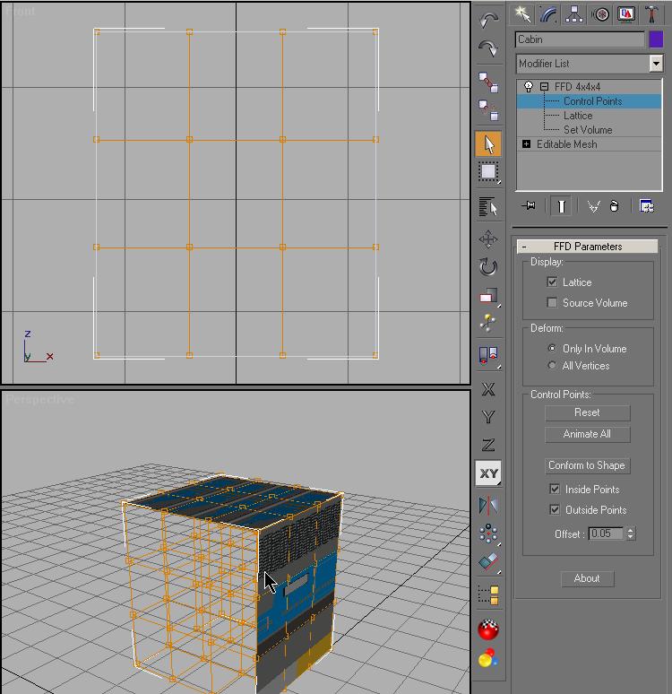
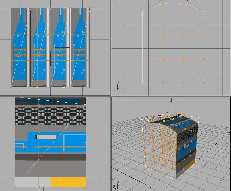
Now you can manipulate and shape the roof section of the Cabin.
Add a FFD 4x4x4 modifier to the stack. This is a
Free Form Deformation modifier. The 4x4x4 defines
a 4x4x4 matrix of control points to manipulate the shape.
Expand the modifier using the + next to it and select Control
Points. |
 |
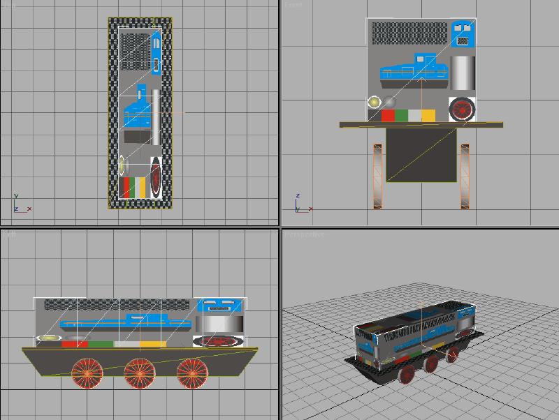
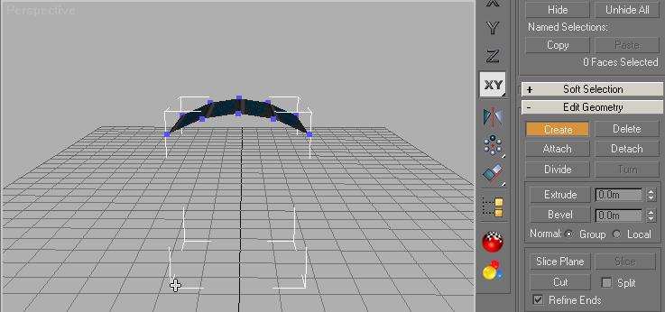
For this operation, I find it easiest to start with the Front
Viewport.
HINT !! You can maximize the active
Viewport by using the Min/Max toggle. This is
located in the extreme lower right hand part of the GMAX
interface.
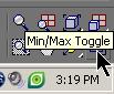 It is hard to get a capture of the actual symbol.
I am using this the following illustration.
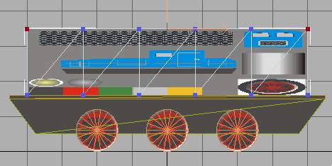
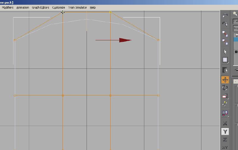
Zoom and position the Roof for
a better view. Using the Move tool, and restricting movement to
the Y axis, select the center sets of Control
Points on the top, or roof section of the Cabin. The selected Control Points
change color from orange to yellow. Move these up to achieve a
curvature to the Roof.
This is not a precision move, since you have no dimensional data
available. Don't extend this too high, or you will have difficulty
when you texture the front of the Cabin.
|
 |
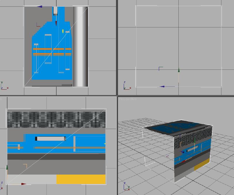
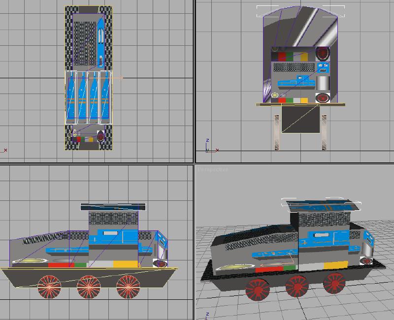
| Switching back to view all 4 Viewports, using the
Min/Max Toggle; you see the roof section is now curved. |
 |
| You can now collapse the stack and the you will add the front and back
sides to the Cabin. |
With the Cabin selected, in the
Modify mode, you use Polygon select. Use
the Perspective Viewport. Rotate and Zoom
to show the Cabin in approximately the same position as shown in the
illustration below.
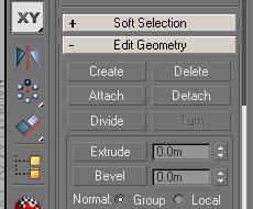
Click on Create in the Edit Geometry
rollup. You will see what appear to be vertices appear. You
will use these vertices as the points to outline the new surfaces for
the Cabin's front and rear. |
 |
Caution!
It is essential to create the polygons
in a
counterclockwise
direction.
Otherwise the Normals would face to the other direction and the polygon
would not be visible from the outside.
Reference :
Normals
are used to define which side of a face or vertex is considered the
"out" side. The out side of a face or vertex is the side that's visible
in viewports.
|
|
When you move the mouse pointer into the Perspective Viewport,
you see a thin cross hair cursor.
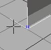
As you move over a vertex, the cursor shape will change to a small
cross. This
will aid in selecting any vertices that are not visible in the viewport. This
will aid in selecting any vertices that are not visible in the viewport.
|
2 of the vertices do not show. There are 2 on the
bottom part of the side, one in each corner. The illustration
above shows one in the lower left corner. There is another on in
the lower right corner. The cursor in the picture is a small
cross. When the cursor is moved off one of the vertices, it will
change to a cross-hair cursor. The 5
alignment points on the roof section are very difficult to locate if the
shape is not oriented as shown in the illustration.
Start with any vertex you want, but be sure to work in a
counter
clockwise direction. Click on the first vertex and move
to the next and click again, when your cursor changes.
Click once on each of the vertices in a counter clockwise sequence.
A thin dotted line follows your cursor's movement. When you are
over the last vertex, double click to complete the creation of the new
face.
This is the result:
|
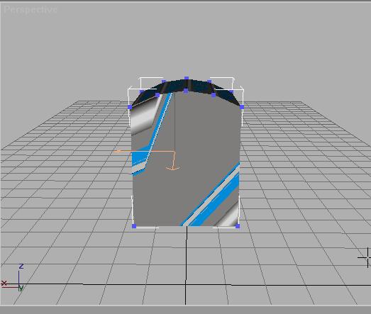 |
Rotate the shape in the Perspective Viewport
to show in the same manner as the first side. You wont see the
shape you just added, because the normals for that side are facing the
other way.
Follow the same procedures as you did for the Front (working counter
clockwise) and you will see the other side of the Cabin added. |
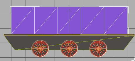
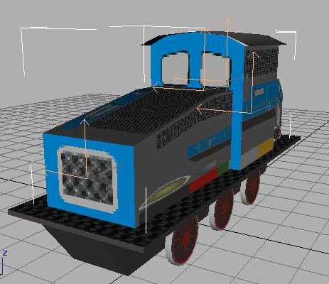
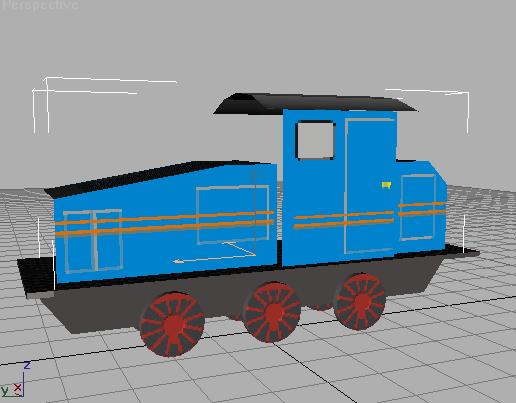
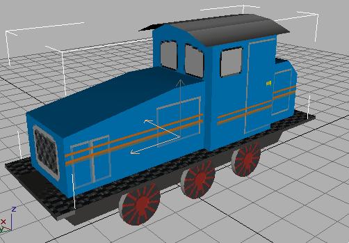
Now if you rotate the shape in the Perspective
Viewport, you will see that you have all 4 sides on the
Cabin.
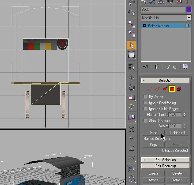
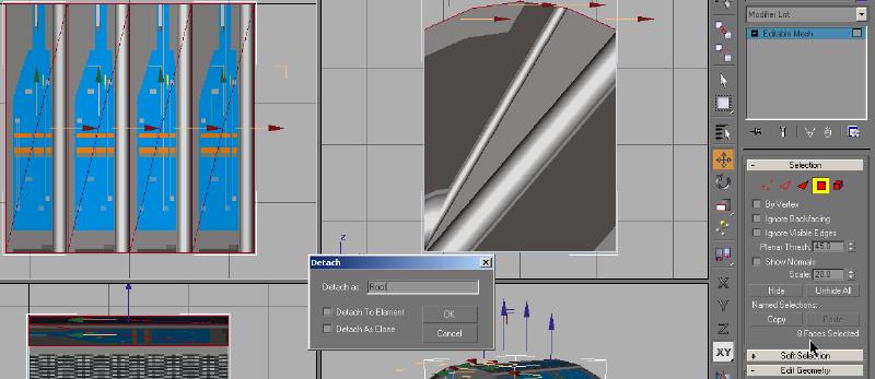
You are now ready to stretch the roof over the sides of the Cabin.
You should still be in the Polygon select mode.
In the Top Viewport, select the 8 polygons of the Roof.
(the cursor in the illustration below point to the area that shows the
number of selected faces, or polygons) Now, click on
Detach and name the new object Roof. |
 |
Stretching the roof
To insure that you do not stretch the Roof beyond the
edge of the frame (Main), you will unhide all the hidden
parts of out loco. In the Display mode, click on
Unhide All. You now see all the parts you have
made up to this point. You should not have to Zoom Extents.
You will be using the Top Viewport to stretch the
Roof. |
|
Go back to the Modify mode and
de-select the Polygon selection mode and select the newly detached roof
using the Select List  on the Tools menu. In the
the Modify panel, click Vertex
select
on the Tools menu. In the
the Modify panel, click Vertex
select
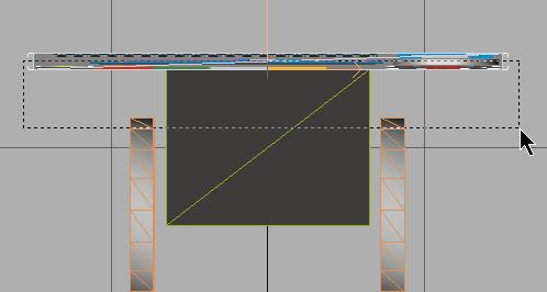
Our goal is to both stretch the length of the
roof and to widen the roof over the edges of the cabin. Select the
Top Viewport. Click on the XY-Axis
 in the toolbar. This will restrict movements to the X-axis
and Y-axis only. Select all the roof's vertices and stretch
them with the Non Uniform Scale tool.
in the toolbar. This will restrict movements to the X-axis
and Y-axis only. Select all the roof's vertices and stretch
them with the Non Uniform Scale tool.
 This is another "eye-ball" move, with no specific dimensions. I
used the edges of the Frame as my guide. As you
move this you will see the changes in all the Viewports.
This is another "eye-ball" move, with no specific dimensions. I
used the edges of the Frame as my guide. As you
move this you will see the changes in all the Viewports.
|
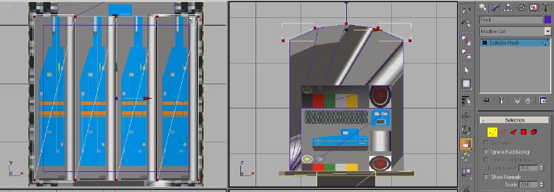 |
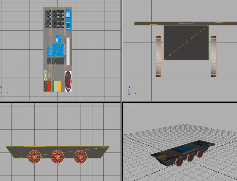
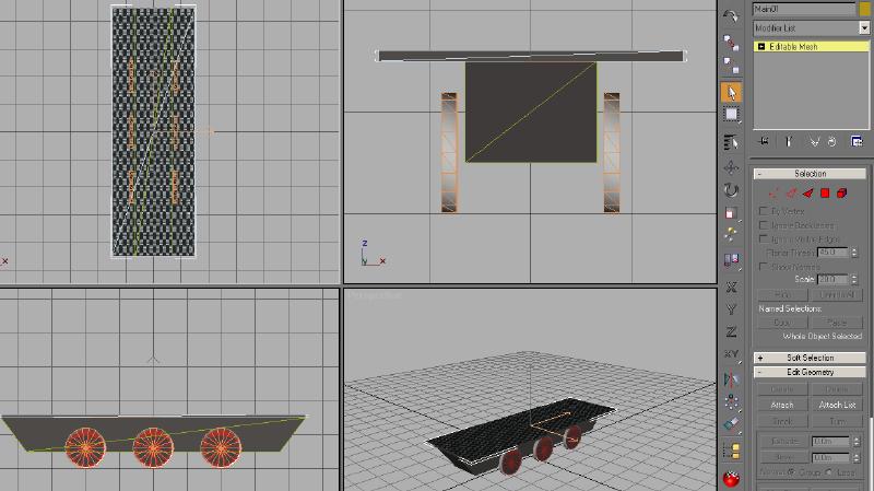
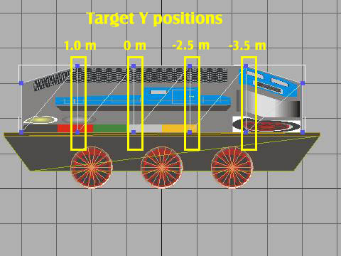
| Still in the Vertex select mode, you can use the
Move tool and the Move Transform Type-in
to select and move the front and back vertices to a position that you
feel looks right. Zoom all Extents and your
model should look something like this: |
 |
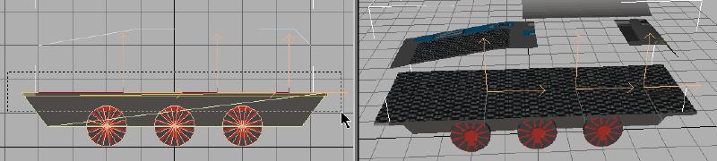
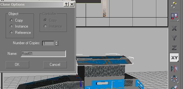
The faces of the roof are only visible from above due to the
direction of their normals. To make the under side visible (when you are
inside the cab), you have to copy
the roof and flip its normals. To do so, you deactivate the vertex selection mode
and with the Move
tool activated, you Shift-Click on the roof
to make a copy.
|
 |
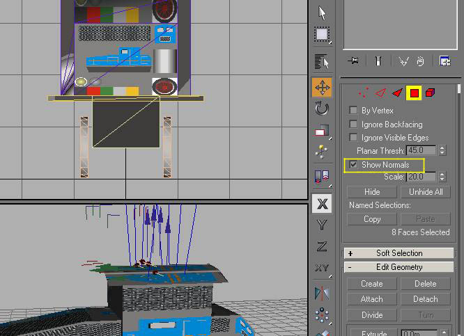
Then you switch to Polygon selection mode (the new object
Roof01
is selected automatically) Select all the Roof01 polygons.
As another aid, you can check the box next to Show Normals
in the Modify Rollup. This will show you the
directions of the existing Normals.
|
 |
|
Scroll the Modify rollout down until you see the
Surface Properties section. In the
Normals section
you click the
Flip button. |
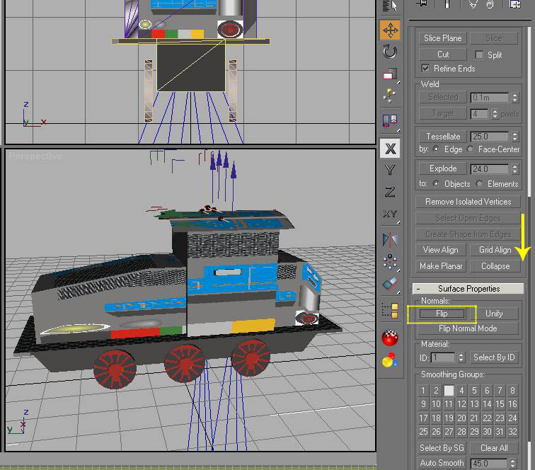 |
| You can see the direction of the Normals for
Roof01 have changed and it can now be seen from below. |
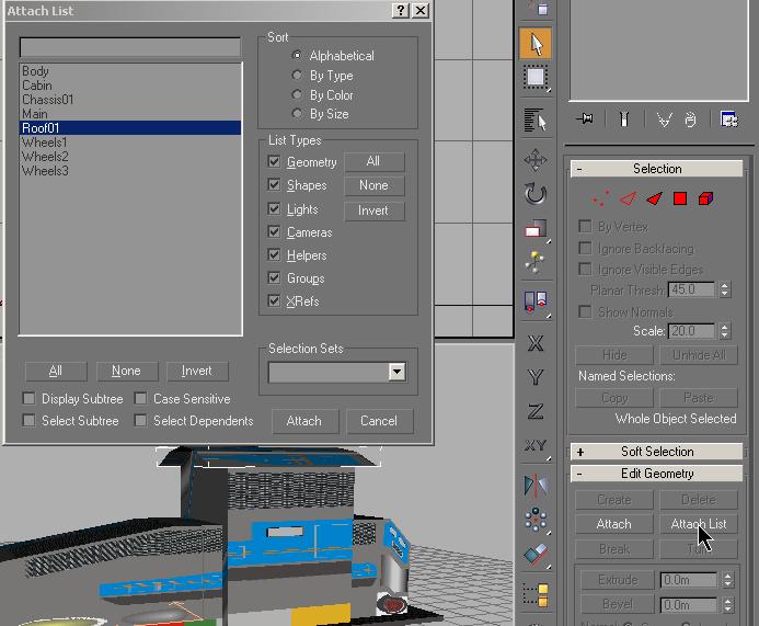
You deactivate the polygon
selection mode and select the primary roof object Roof
Select List . Then
you attach
the object Roof01 with the roof using Attach List.
|
 |
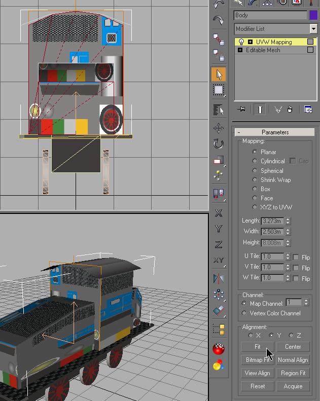
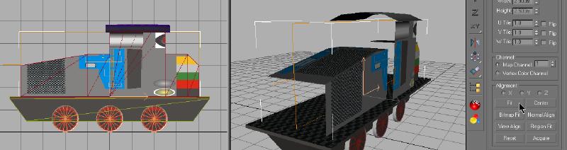
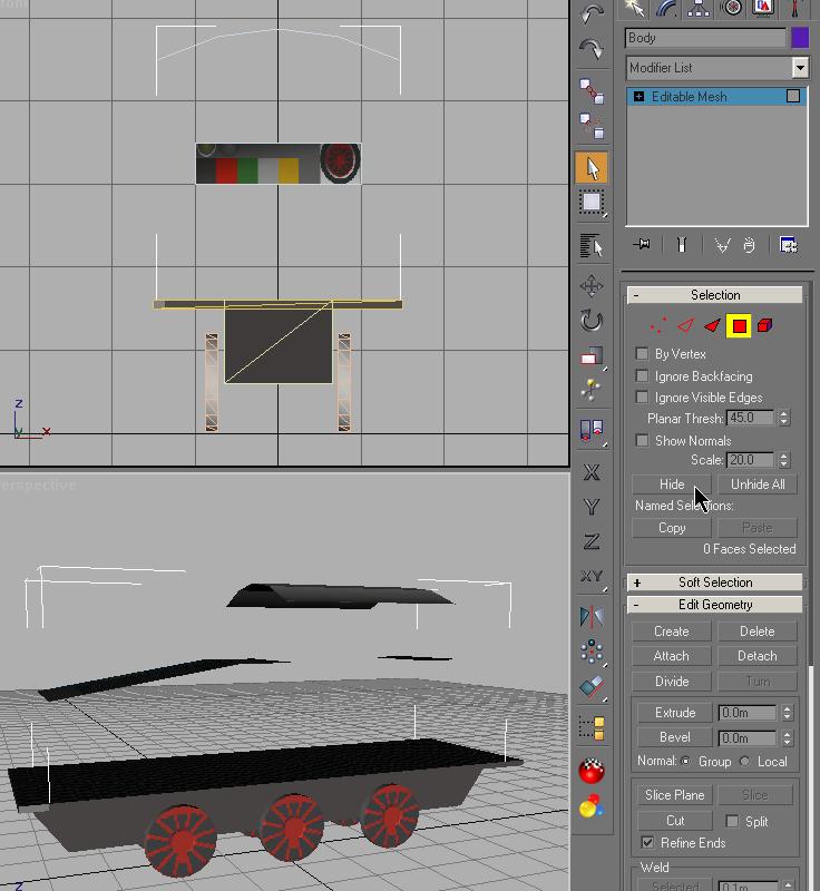
With the selected roof you change to the polygon select mode and
select
all the polygons of the Roof. You should show 16
faces selected. You add the
UVW Mapping
modifier to the stack. This should the Alignment set to Z. Then
you add the
Unwrap UVW modifier
to the stack and select Edit.
|
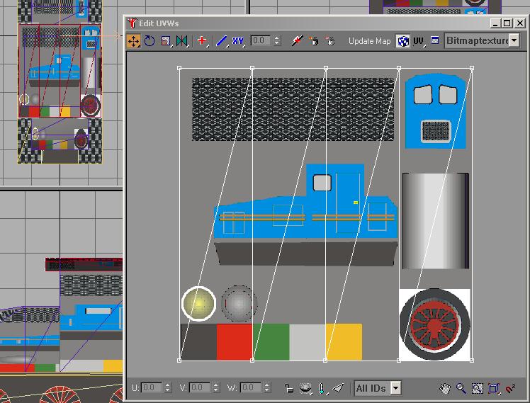 |
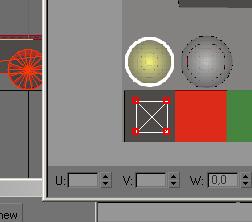
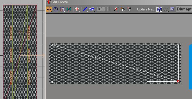
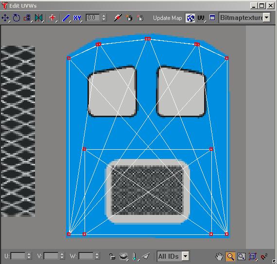
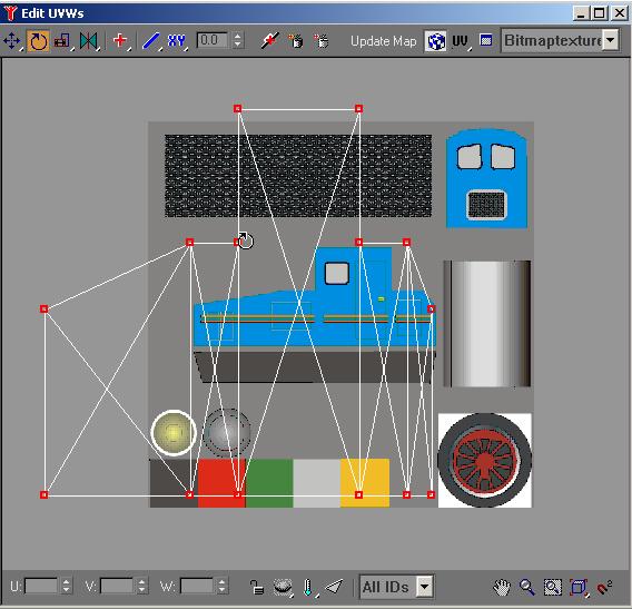
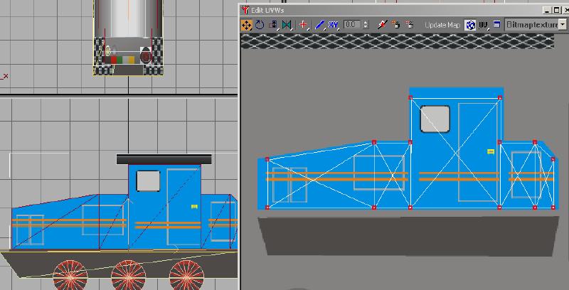
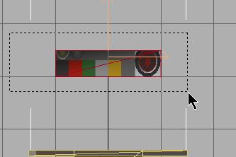
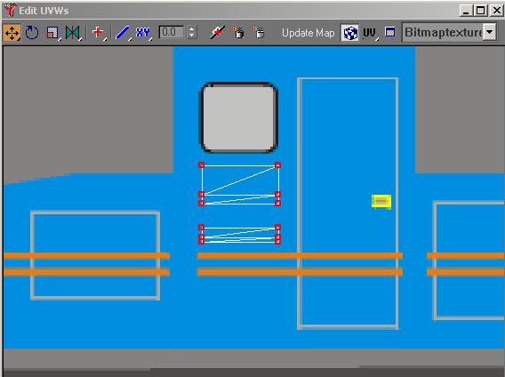
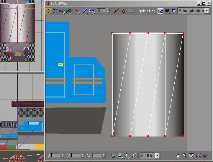
With all the vertices selected in the editor, you resize and move the mapping vertices
to the roof section of the image. OK, you can't get the mapping
vertices to line up correctly using the tools you know. You will
use a new tool to get the alignment you want.
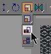 This
is the Horizontal Scaling Tool in the UVW mapping
editor. It will stretch or contract the selected mapping vertices
along the horizontal axis only. The other tool not used here, but
shown in the illustration is the Vertical Scaling Tool
that does the same thing on the vertical axis. This
is the Horizontal Scaling Tool in the UVW mapping
editor. It will stretch or contract the selected mapping vertices
along the horizontal axis only. The other tool not used here, but
shown in the illustration is the Vertical Scaling Tool
that does the same thing on the vertical axis. |
| Using the Scaling Tools and the Move Tool, align the
mapping vertices as shown below. Zoom and move the image to get
the placement of the mapping vertices as accurate as possible. |
 |
You can now close the editor and collapse the
stack. You are finished with the roof.
We can now join the Roof, Cabin and
Body into a single shape.
Use Select by Name
to select the Cabin. In the Modify rollup, use
Attach List to attach the Roof to the Cabin.
Select the Body and attach the Cabin
to the Body. |
| Save your project and you will continue on to map
the Body. |