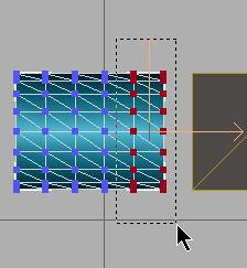
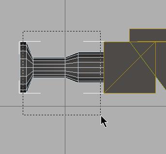
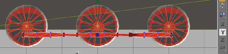
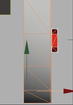
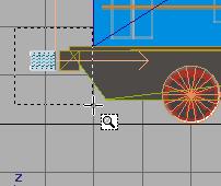
Then, with movement restricted to the
X-axis you align the vertex rows with the
Move tool.
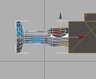
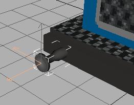
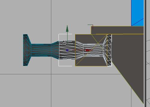
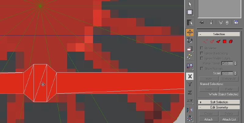
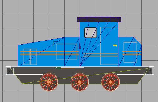
Rather than doing this entire operation by eye, you
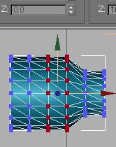
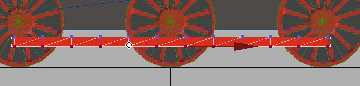
can create the first connecting point visually by focusing you your view
to the left side of the rod, and the 1st 4 vertices..
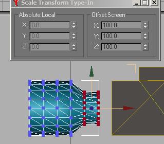
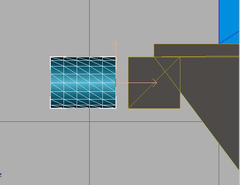
Shape an approximate rod connection point by moving the vertex pairs.
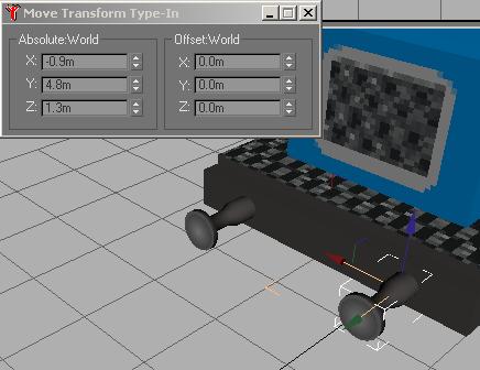
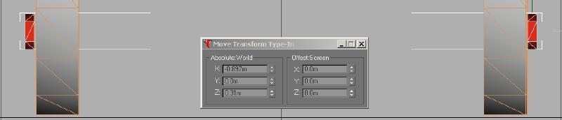
This doesn't need to be perfect, just a rough approximation. Using
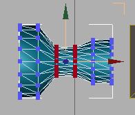
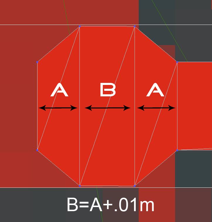
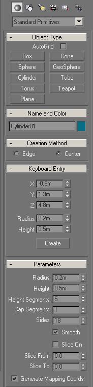
the Move Transform Type-In, set the distance
between the 1st and 2nd setss of vertices and the 3rd and 4th sets of
vertices to the same value. Set the distance
between the 2nd and 3rd sets of vertices to a larger value.
On my model, I found that a difference of .01m
gave the best results.
HINT !!
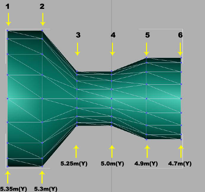
Write down the Y values for each pair when
you have the distances set. This will be used to set the remaining
vertices positions. Set up a matrix to calculate the values that
you will use for the other 8 pairs of vertices to create symmetrical,
equally spaced connecting points.
| |
Vertex Pair |
1st Connection |
Vertex Pair |
2nd Connection |
Vertex Pair |
3rd Connection |
| Y Position |
1 |
x.xxxm |
5 |
x.xxxm |
9 |
x.xxxm |
| Y Position |
2 |
x.xxxm |
6 |
x.xxxm |
10 |
x.xxxm |
| Y Position |
3 |
x.xxxm |
7 |
x.xxxm |
11 |
x.xxxm |
| Y Position |
4 |
x.xxxm |
8 |
x.xxxm |
12 |
x.xxxm |
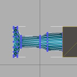
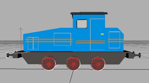
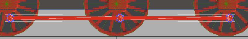
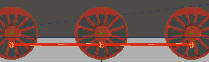
Our wheels are positioned at 2.0m
intervals. Using the initial Y position values you record for the
1st Connection point, you calculate and record the values for the other
Connection points. Subtract 2.0m from the 1st Connection point to
get the value for the 2nd connection point and then subtract 2.0m from
the 2nd Connection point to get the value for the 3rd.
As an example:
| |
Vertex Pair |
1st Connection |
Vertex Pair |
2nd Connection |
Vertex Pair |
3rd Connection |
| Y Position |
1 |
1.99m |
5 |
-.01m |
9 |
-2.01m |
|
|
|
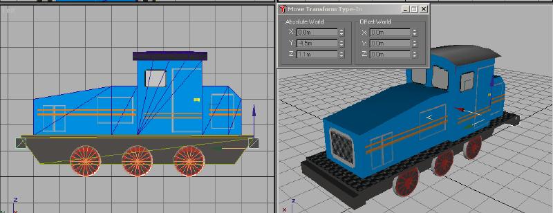
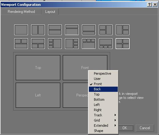
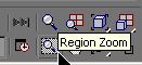
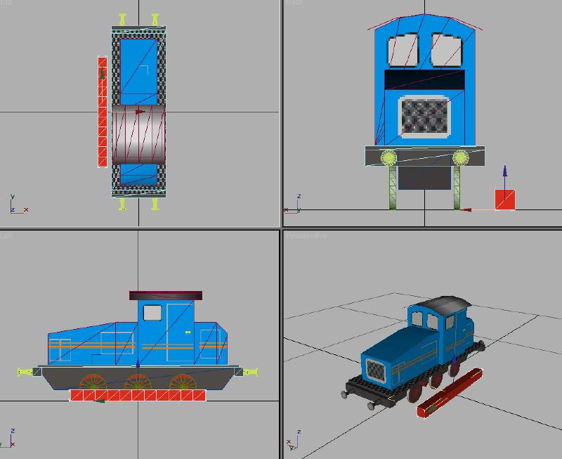
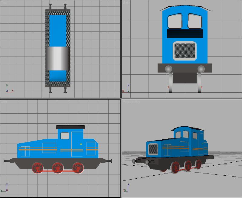
 to focus on this Viewport