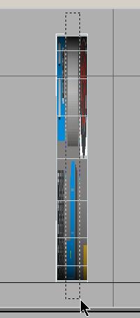
3. Simple Construction - A Diesel Loco - Part Three


Version 2.0 - May 2008

The chassis gets wheels

To create a wheel, you use a Standard Primitive again. This time a Cylinder. Make the Left Viewport the active Viewport (click anywhere in the Viewport and the border turns white), you create a Cylinder.  The parameters are shown below:


You create the cylinder with the Keyboard Entry method. You open the Keyboard Entry rollup by clicking on the small cross. The following parameters are now to be typed in:

  • Radius: 0.6 m
  • Height: 0.15 m
  • Height Segments: 1
  • Sides (number of polygons around the wheel, the tread): 18
  • Generate Mapping Coordinates must be selected.

One click on Create and here you are. The wheel is sticking halfway in the ground and is positioned in the middle of the virtual world. That doesn't matter yet. First, you have to convert the wheel into an editable mesh. As you did with the chassis, you right-click onto the wheel and in the Quad menu you choose Convert to - Editable Mesh.


Hiding the chassis

The wheel is partly hidden by the chassis. Therefore you will hide the chassis temporarily. You select the chassis only and in the

 Display toolbox         you click Hide Selected. The chassis is still existent but hidden.


To have the wheel shown as big as possible in all the viewports, you click Zoom Extents All within the view control.


Hint :  Keyboard Shortcut :  Ctrl-Shift-Z.


Now, you see the wheel in all Viewports.   You may see only part of the wheel in the Perspective Viewport. Or not at all.


The easiest way to correct this is to change the Perspective Viewport setting to the User Viewport

Right-click on the Viewport name (Perspective) and select Views in the menu that pops up and then select User


Setting the pivot point

In the front viewport, you see, that the pivot point of the wheel lies in the center of the world rather than in the center of the wheel. You have to change this in order to have the wheel positioned correctly.

To do so, you go to the Hierarchy toolbox.


Click Affect Pivot only, Center to Object and Align to World. Then you deselect Affect Pivot only.


Now, you can select and move the wheel. A right-click on the Move symbol     opens the Transform-Type-In dialog box.. There you enter these values:

  • Absolute World X: 0.8 m (slightly more than half the track gauge)
  • Absolute World Y: 2 m (first wheelset, 2 meters in front of the center)
  • Absolute World Z: 0.647 m (Wheel is lifted by the radius' value + rail height)

Then, you click Zoom Extents All again.


NOTE : You may have to adjust the magnification in the Perspective Viewport to see the entire shape.  Use the Zoom Tool (magnifying glass) for this.

Since you have hidden the Chassis, it may be hard to get a good perception in your mind about what all these positioning changes are doing to the wheel in relationship to the Chassis.  Here is what you have just done:


CAUTION !!
I suggest that you save your project at this point.  If you experience any problems in the texturing section, you can restore to this point and not have to repeat steps you have already done.

Texturing the wheel

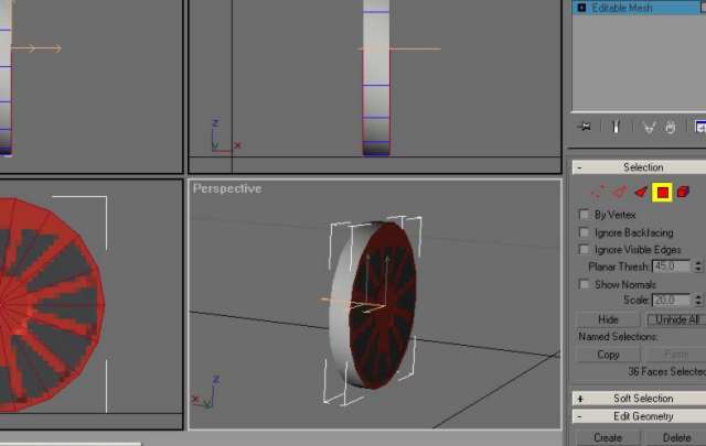
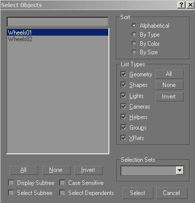
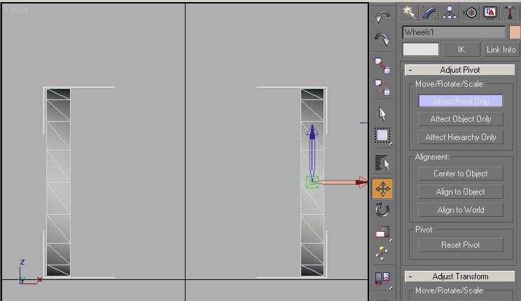
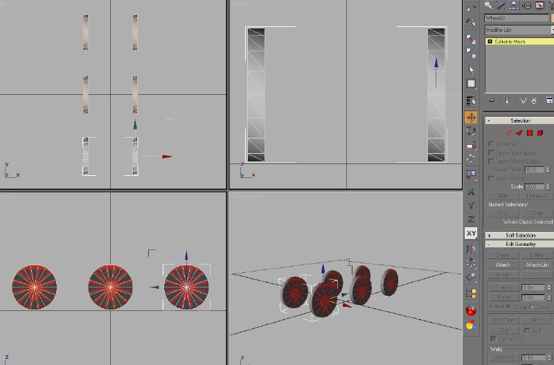
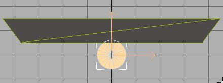
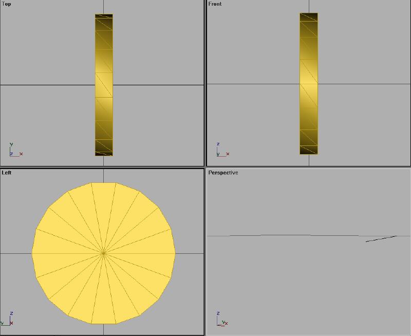
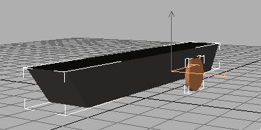
First select the wheel in any Viewport.

You already opened and used the texture file that you will use throughout this project, so there is no need to load it again.
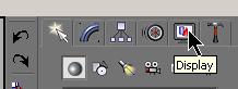
You will use the Material Navigator  This is just below the Material Tool. Open the Material Navigator.


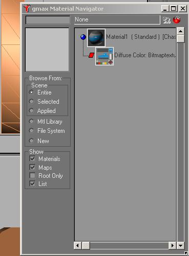
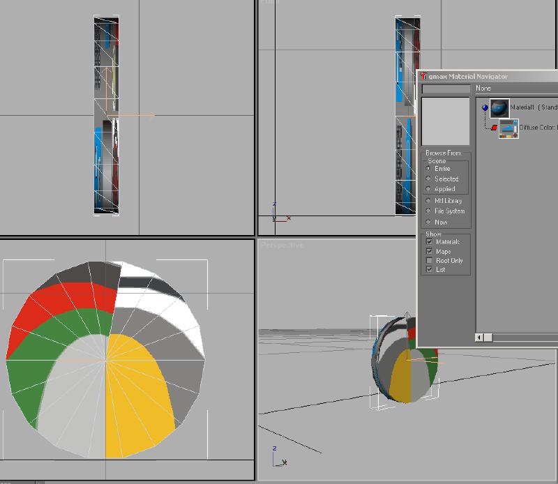
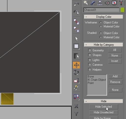
You can see that the same material that you used to texture the Chassis is shown.  Any time you use any ACE file texture in a project, the material is saved in the Material Navigator.  I cannot elaborate on the entire scope of the use of the Material Navigator.  I have not fully investigated the scope of its use and/or capabilities.  Feel free to read through the HELP section on your own to become more familiar with it.

You don't need to open Material Tools to apply a texture that has already been used in a project.

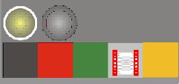
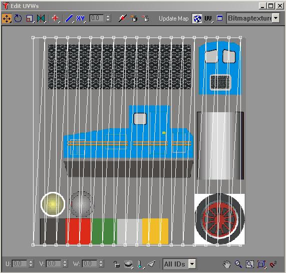
Click on the image of Material1 and it will appear in the window to the left wrapped around a sphere and the line will be highlighted.  You will also see that Apply Material to Selected Object is no longer grayed out. 


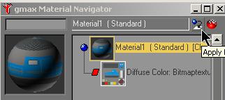
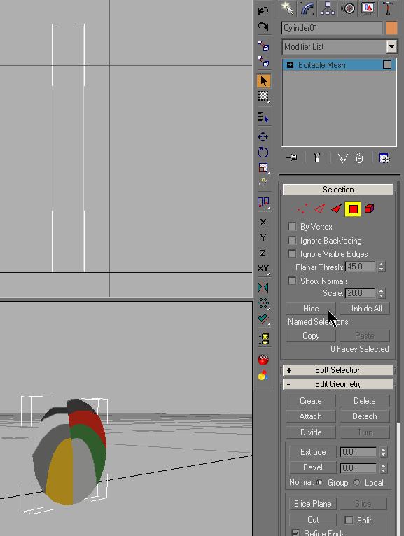
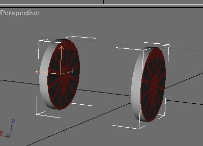
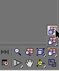
Click on the Apply Material to Selected Object icon and the texture will be applied to the wheel

Now you can close the Material Navigator.

You will map the tires first...

Select the wheel in the front Viewport. Using the Modify Tool     you use the Polygon Mode 


Use the Mouse Pointer (Select Object) tool and select the entire tread area (from top to bottom) starting outside the shape on the top left and ending up outside the shape at the bottom right.  Be careful not to include the sides in your selection.

You should now see the polygons selected in red in the Front and Top Viewports only. 
 

In the modifier list, you select UVW Map, the parameter X, and you click the Fit button.

Then you select Unwrap UVW and open the mapping editor.


You select all the vertexes by drawing a box around them.  All the vertexes should change color to red. 

Using the Scale and then the Move tool , you map the treads to the light grey rectangle an the bottom right of the image.


Then you close the editor and collapse the modifier stack

 Right-Click in the area below Editable Mesh and select Collapse All.  Select Yes on the warning screen.


...texturing the sides of the wheel

Again, you switch to polygon mode without clicking into any viewport. The tread polygons are still selected. You click the Hide button. The side polygons ought still be visible.


In the Perspective viewport you see, that the back-facing sides of the polygons are invisible. This is due to the direction of their normals. In the Front and Top viewport, all polygons are to be seen by their red edges.

Now, you select all visible polygons by dragging a box around them, (Remember? Switch to polygon select mode first.) and select UVW Map in the Modifier List menu. Then select the Z axis in the Alignment section and click on Fit.


The image will appear as below.


In the list menu you select Unwrap UVW and open the editor. There, you use the scale and move tool to adjust the shape. The Scale tool also contains tools to scale horizontally or vertically only.

The image can be panned or zoomed with the view control at the lower right edge of the editor. The result should look like this:

Here you can see why so many of today's content creators use larger texture images than 512 x 512.  Not only for accuracy in mapping textures, but the image quality itself is so much better.  When MSTS first came out, the average computer system was not capable of efficiently handing content created with large sized textures.

You close the editor and collapse the editor stack. Then you switch to Polygon mode and click the Unhide All button. The tread becomes visible again.


You deselect the polygon mode by clicking on the polygon symbol and rename the part from cylinder01 to Wheels1.

The first wheel is done!

HINT !!
Don't hesitate to save your work at any point during the project.  Saving at any point can save you a lot of rework if you make any mistakes.  I won't be prompting to save your work at any point.

Making a wheelset from a wheel

To copy the wheel, select the Move tool. Then, press and hold the shift key, click on the wheel. The copy dialog appears. Here you select Object Copy and click OK.


Now you have two wheels, Wheels1 and Wheels02.  Both are occupying the same space, so nothing appears to change.

Wheels02 is selected automatically.


You right-click onto the Move symbol which activates the Move-Type-In dialog box and change the X-value from 0.8 to -0.8. The whole wheel has moved.


One click on the Zoom Extents All symbol or Ctrl-Shift-Z and both wheels are visible in the viewports.


You select the other wheel (Wheels1).

HINT !!

As you get  more objects in the project and visible on the screen, it can be difficult to select the one you want using the mouse.
You can select objects with the
Select dialog. To do so, you activate the Select by Name      symbol or press the H button. 
This next image shows the Select dialog mentioned in the Hint above

In the modifying tool, you click on the Attach List button to be found below the Edit Geometry section


Here you select Wheels02 and click Attach.


The first wheelset is done.


Now you should adjust the pivot point.  Switch to the Hierarchy section and select Affect Pivot Only and you will see that the pivot point is still centered to the first wheel, not the wheelset.

Click Center to Object and then Align to World and you will see the pivot point shift as shown below.

 
Now you can de-select Affect Pivot Only and leave the Hierarchy mode.

Now you copy the whole wheelset by first selecting the Move mode and then Shift-Click on the object. In the dialog box which appears, you choose the option Object Copy and Number of Copies 2 and hit OK.


With the H key and the select dialog, you select Wheels02 and move it with the Move tool and Transform-Type_In to a Y value of zero meter.

You rename the wheelsets to remove the zeros from the names.  (example: Wheels02 to Wheels2) 

See the Creation of a Complex Shape.doc that is part of the self extracting file TECHDOCS.EXE included on the MSTS installation CD-1 in a folder named TECHDOCS.  If you have not extracted this to your C:\Program Files\Microsoft Games\Train Simulator\HELP folder, it is recommended that you do it now.  If you have extracted it already to a different location, that is fine.

This document, although not the best written tech doc you will find, explains the hierarchy and naming conventions used for MSTS models. 


You do the same procedure to the Wheels03 object:

  • select Wheels03 with the H dialog
  • move with Move Transform-Type-In to Y -2 meter (minus 2.0 meter)
  • rename object from Wheels03 to Wheels3
  • Don't forget to rename Wheels01 to Wheels1

Renaming the Wheels is critical.  The animation in MSTS will not be correct if this naming convention is not used.

You now see this in our viewports after Zooming all extents.... 

Unhide the chassis

In the Display toolbox, you unhide the chassis by clicking the Unhide All button. Zoom Extents all gives us the right view.

Chassis and wheelsets are now ready.

Now, save your project. 


back to the table of content

to part 4