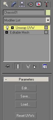
3. Simple Construction - A Diesel Loco - Part Two


Version 2.0 - May 2008

Coloring

Gmax with the MSTS plug-in is the only software capable of exporting models into MSTS without any texture. The models would be shown in white colors only. Therefore you ought to paint our model. This means to put parts of images or drawings onto each face or polygon. This is called texturing. The texture in conjunction with other properties, such as lighting parameters, make the material which is put to the faces.

The images have to fulfill certain requirements in order to be used in MSTS:

  • They have to be square shaped rather than rectangle shaped.
  • Its size has to be 32x32 or multiplied by two. (64x64, 128x128 and so on)
  • Maximum size is actually unknown.  512x512 is common and 1024x1024 is being used extensively today as well.  I have seen ACE file textures used as high as 2048x2048
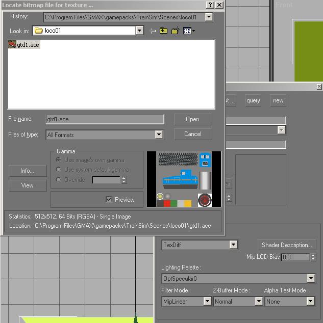
  • only the MSTS-Kuju .ACE-format is allowed
  • Transparency map (one Alpha-channel) is allowed

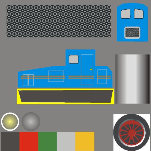
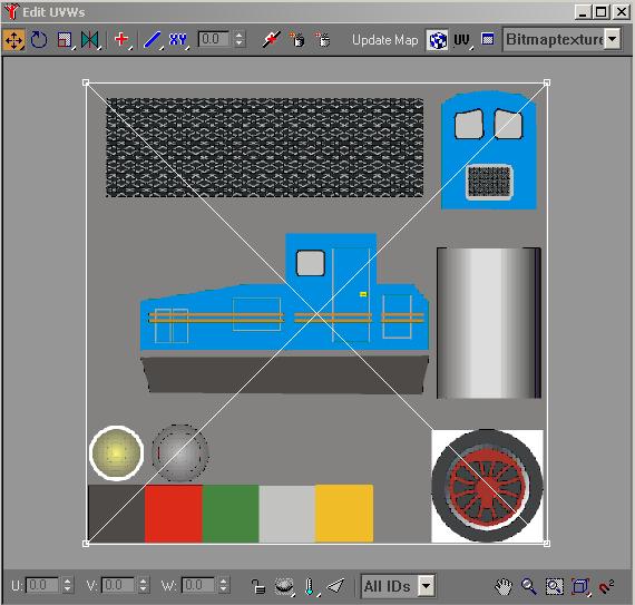
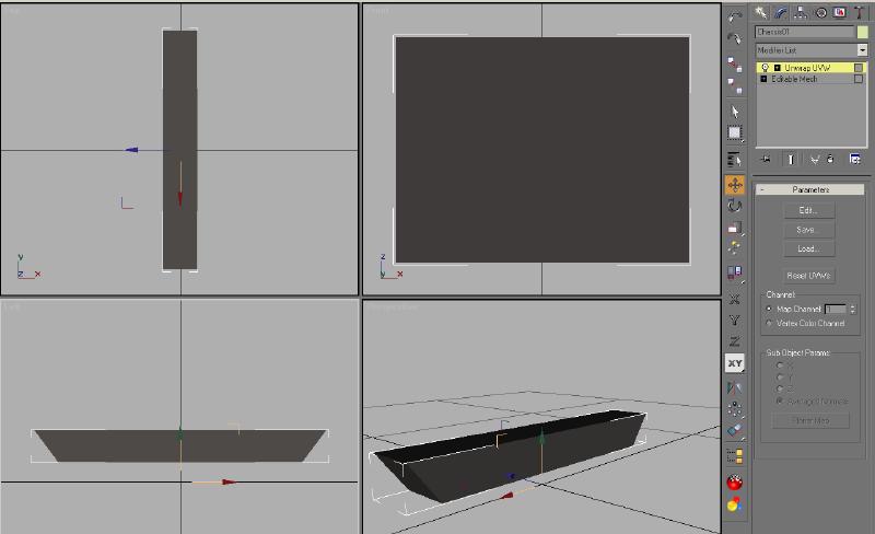
The image you are using, is 512x512 pixels in size and looks like this:

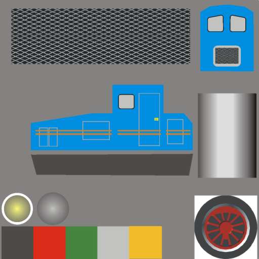
The image file can be downloaded here. It has to be unzipped and copied into our loco01 folder.

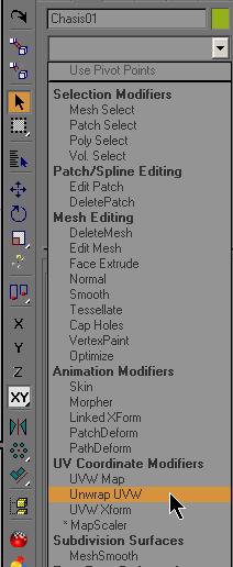
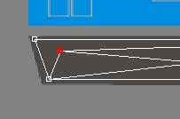
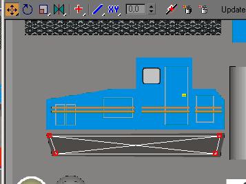
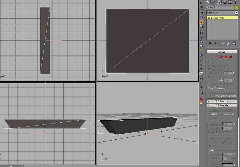
The dark grey conic shape below the loco's side view shall now be mapped onto the sides of the chassis.


Creating a material

First, you have to create a new material. Thus, you open the material tool with the according symbol:

The material tool window:


A click on the New button, and you can give the new material's setting.


In the Name field, you type in Material1. Then you click Texture open.

Here you change into the loco01 folder and choose the image gtd1.ace.


The texture image file is now loaded, and you leave all other settings as they are.


Putting a material to an object

Now, you select the chassis and in the material tool window you click Put! once. The image has now applied to all sides of the chassis.


very colorful indeed...

WARNING !! 

Failing to check  Generate Mapping Coordinates will cause you problems when you try to map a texture to the shape.  You will only see a gray color, not the image.
To correct this problem see the Appendix, Section 2.

...but not really what you wanted. GMAX puts the image with all its extents to each side of the chassis. What you need is only a small selection of the image rather than the whole thing.  This is the gray section outlined in yellow in the image below

 
To apply only a part of an image to a face or a selection of faces or polygons, is called mapping. Gmax allows to map a number of polygons at one time, provided, they belong to the same object. Since our Chassis is a single color, you map all the polygons of the Chassis at the same time. 

Mapping

In this case, when you applied the texture to the shape, the texture is properly oriented to the shape, so you do not have to re-orient the texture to the shape.  You only want a part of the image to be applied to the shape.  Since this part will be all one color, alignment of the highlighted area is not critical.  In future sections, where you are mapping the wheels and the cab to the texture, the alignment becomes more critical.


You want to map a part of the image only. Therefore, in the Modifier List you choose Unwrap UVW.


Here, you click the Edit button and the Mapping Editor shows up.


Then you select multiple vertices by dragging a box around them. Selected vertices change color to red.


Now, you have to align the selection with the correct section of the image, which is the dark grey polygon underneath the side-view. With the Move tool selected as shown in the illustration above, you select the mapping vertices by drawing a box around the vertices you want to move. The selected vertices turn red.  Move the vertices of each of the corners into the correct positions.

Caution!!

Do not try to select the vertices by clicking on them. Doing this, will select only one vertex of two (Remember, vertices of the left and right side of the chassis are on the same position when viewed from the side) and the result will look something like this:


When all vertex pairs are moved correctly, the editor window should look like shown in the next image.


Once all points are aligned properly, the editor can be closed.  When doing a completely solid color texture, as you are doing for the Chassis, the alignment of the points vertices in the editor are not that critical.  As you continue to the wheelsets, body and cabin for the loco, this alignment does become more critical.  Poor texture alignment will not produce a very good model, regardless of the quality of the mesh.


The Chassis is mapped. Now you collapse the modifier stack.

To do this, you right-click into the grey field right underneath the Text Editable Mesh. In the context menu you choose Collapse All


A warning appears where you click Yes...

...and the Chassis is mapped.


The chassis is now textured. You may now deselect the object and save our project.


Congratulation

The first object is finished


back to the table of content

to part 3