charland, on Oct 24 2008, 07:11 AM, said:
When I was finished drawing the model I opened the shape file in sView, used their Bounding Box information to get the following with 1 meter removed from the length as I recall reading this somewhere.
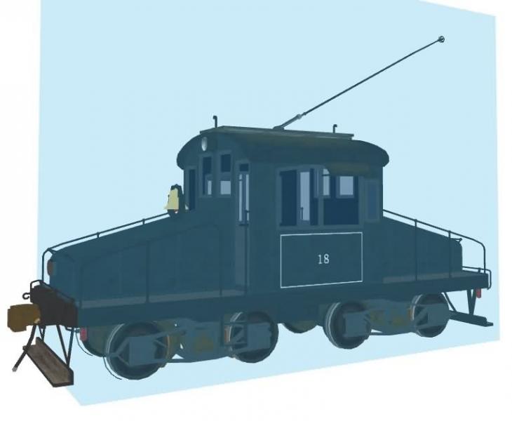
InertiaTensor ( Box ( 3.139m 5.898m 7.673m ) )
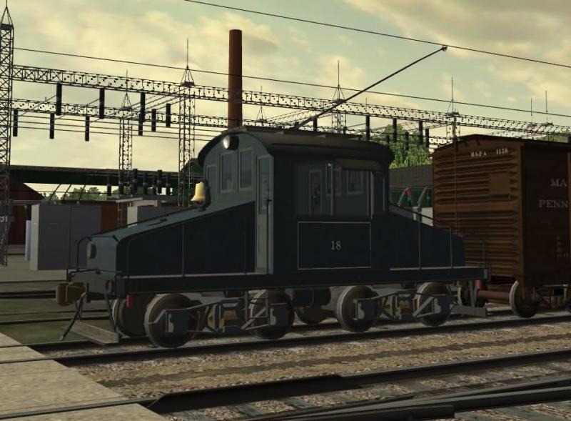
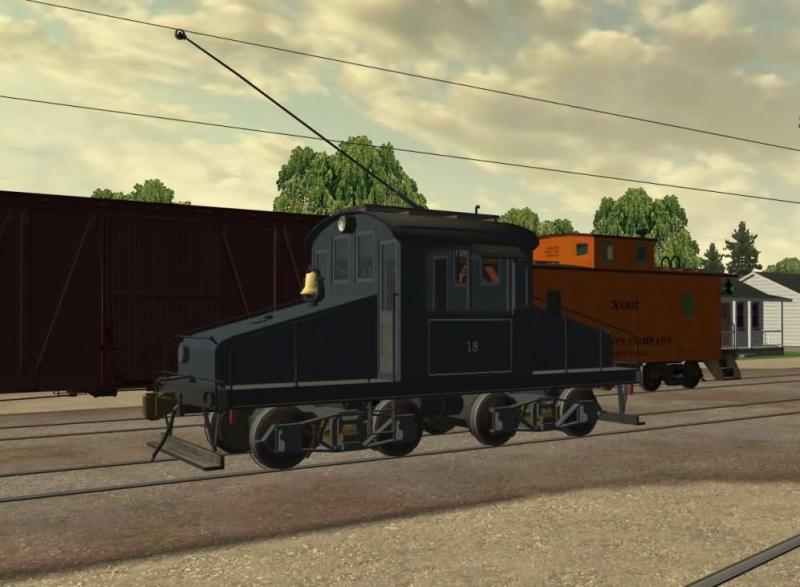
I then set up a small activity in the Dogbone Route to stop and lift a car, checked the coupler spacing and it looked fine to me. Are you getting you're information through another program and where would you put this in your enging file?
Paul,
The InertiaTensor statement has nothing to do with the coupler spacing and how things look and hook up. The Size statement does it, and based on your visual experiment and the screenies above, that looks OK.
Imagine that the Box statement buried in the InertiaTensor instruction defines just that, a rectangular parallelapiped in the shape of a brick. The quantity specified in the Mass statement is homogenously distributed throughout the brick. The brick is given the ability to rotate about all three (x,y,z) axes with the center of rotation being at the centroid (center of mass). You can determine where the centroid actually is by examining the ESD_Bounding_Box statement in the *.sd file.
The InertiaTensor defines how the brick responds to changes in angular (rotational) momentum or inertia. Remembering Newton's First Law of Motion: "Every object in a state of uniform motion tends to remain in that state of motion unless an external force is applied to it." This is also known as the "Law of Inertia" and applies to both linear and angular inertia.
Imagine that the brick is moving along a tangent; angular momentum is zero. A curve is encountered, and the brick's response is to resist. Think of the wheel flanges as being at the ends of levers which apply the force needed to get the brick rotating. Once rotating, the brick has angular momentum and wants to continue to rotate. The whole process operates in reverse when the next tangent is reached and angular momentum must be reduced to zero again.
Based on some exp'ts I did with large changes to the InertiaTensor statement a number of years ago, I bet that the small change you made will produce no observable effect on train handling. In theory, the reduction you made has concentrated the homogenous mass closer to the centroid and should make it easier to change the rotational inertia. However, it isn't as if we're trying to modify the angular momentum of a high performance jet aircraft in a dogfight in a combat sim. :lol: It's best, as the TechDocs suggest, just to leave it the same as your final result for the Size entry.
If you google InertiaTensor, the wikipedia page appears to be OK. The better-known *.edu sites certainly are. This one's entertaining in style at least:
http://baba.astro.co...ertiatensor.pdf
If you wish, just ignore the math/physics bits and read the words. :o
You'll hafta excuse me for this post, but I've been doing this for 42 years. In any event, I have grave doubts about the proper implementation of the InertiaTensor in this sim...
regards,
charlie
 Log In
 Register Now!
 Help
Help