 Log In
 Register Now!
 Help
Help


Additionally, I'm developing a glue program that connects to the Web Server and Arduino devices to allow communication between them, using a text-based protocol. https://github.com/I...leases/tag/v0.1
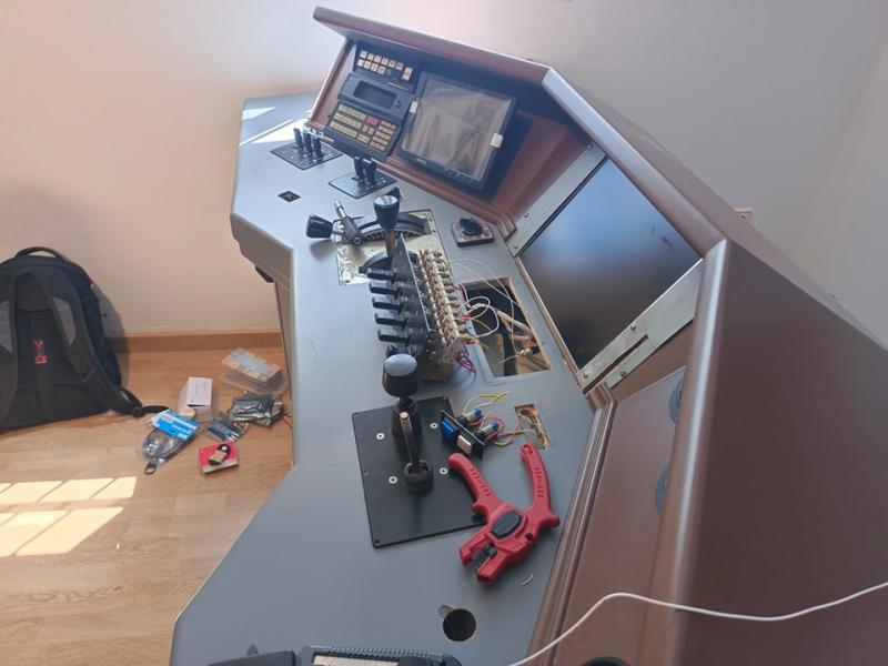
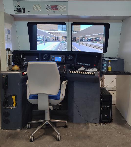
I upload here the Arduino source code we are using. It allows controlling Throttle+Dynamic Brake, Cruise Speed, Train Brake (PBL2 style), Engine Brake, Reverser, Pantographs, Circuit Breaker, Horn, LZB... and it gets information from OR to move two dials (ammeter and line voltage).
I hope I can find some time to write proper documentation for all these things, but in the meantime I'll be happy to answer any question if someone is interested.
Attached File(s)
-
 Mandos252.zip (3.88K)
Number of downloads: 133


