Elvas Tower: Steam Locomotive Additional Features - Elvas Tower

Jump to content

Posting Rules

All new threads will be started by members of the Open Rails team, Staff, and/or Admins. Existing threads started in other forums may get moved here when it makes sense to do so.

Once a thread is started any member may post replies to it.
  • 14 Pages +
  • « First
  • 10
  • 11
  • 12
  • 13
  • 14
  • You cannot start a new topic
  • You cannot reply to this topic

Steam Locomotive Additional Features Rate Topic: -----

#111 User is offline   Traindude 

  • Engineer
  • Group: Posts: Contributing Member
  • Posts: 719
  • Joined: 17-November 13
  • Gender:Male
  • Location:Seattle, WA
  • Simulator:Open Rails
  • Country:

Posted 26 May 2024 - 07:56 AM

View PostWeter, on 26 May 2024 - 06:24 AM, said:

What is "stack talk"?


It's a slang term for the chuffing/puffing sound.

View PostWeter, on 26 May 2024 - 06:24 AM, said:

What the red headlight for?

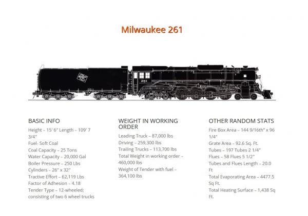
On the 261, the red light is activated during emergency braking warning any oncoming trains that the train has stopped due to emergency braking, and to proceed with caution as there may be workmen on and/or around the tracks.

The reflector of this light actually oscillates so as to draw attention -- this was the days before ditch lights were introduced. These and similar lights were manufactured by the Mars Signal Light Company.

View PostWeter, on 26 May 2024 - 06:24 AM, said:

Through the article about power reversers, You provided, I've found good article about cutoff (and the rest three cylinder events deserve to be learned too)The link have been added to my long post above.
https://en.wikipedia...f_(steam_engine)
https://en.wikipedia...e_(steam_engine)


Now that you mention it, there's something I think would be a good addition to the advanced steam parameters -- valve and valve gear specifications. Many locomotive specifications specify valve events, such as valve travel, steam lap, lead, etc., such as in Railway Mechanical Engineer magazine. (Look at the table on page 105.)

So, we can potentially define valve gear events in a manner such as this:
    NumCylinders ( 2.0 )
    CylinderStroke ( 30.0in )
    CylinderDiameter ( 27.0in )
    ORTSWheelCrankAngleDifference ( 0.0deg 90.0deg )
    ORTSSteamValveMaxTravel ( 7.25in )
    ORTSSteamValveSteamLap ( 1.75in )
    ORTSSteamValveExhaustClearance ( 0.1875in )
    ORTSSteamValveGearLeadType ( "Constant" )
    ORTSSteamValveGearLeadInFullGear ( 0.25in )


You can find more information about valve events in the late Charlie Dockstader's computer valve gear simulation programs.

#112 User is online   Weter 

  • Member, Board of Directors
  • PipPipPipPipPipPipPipPipPipPip
  • Group: ET Admin
  • Posts: 7,437
  • Joined: 01-June 20
  • Gender:Not Telling
  • Simulator:ORTS
  • Country:

Posted 26 May 2024 - 08:01 AM

Before to answer, here's interesting moment, spotted in article:

Quote

If the minimum cut-off provided for by the notches was too high, it would not be possible to run the locomotive in the efficient way described above (with a fully open regulator) without leading to steam wastage or 'choking' of the steam passages, so the regulator would have to be closed. That limits efficiency.


Oh, yeah, "stack talks with skies" - we have such telling here too.

Quote

red light is activated during emergency braking warning any oncoming trains that the train has stopped due to emergency braking, and to proceed with caution as there may be workmen on and/or around the tracks

Oh, so what is "emergency" light condition in *.eng-files for. We use yellow flags and yellow lens on hand torch for that.

Quote

there's something I think would be a good addition to the advanced steam parameters

And, some parameters, e.g. Admission, Lead are already can be seen on HUD, but having an opportunity to define each one, which is known, is greater, than rely on calculations, done by program, which will represent standard results only.

That's obvious fact: each steam locomotive is very individual, due to technologies of it's production, been used. So, that way we could make better reproduction of it by means of ORTS.

Interesting from the article:

wikipedia said:

The throttle is basically a poppet valve, or series of poppet valves which open in sequence to regulate the amount of steam admitted to the steam chests over the pistons. It is used in conjunction with the reversing lever to start, stop and to control the locomotive's power although, during steady-state running of most locomotives, it is preferable to leave the throttle wide open and to control the power by varying the steam cut-off point (which is done with the reversing lever), as this is more efficient. A steam locomotive throttle valve poses a difficult design challenge as it must be opened and closed using hand effort against the considerable pressure (typically 250 psi or 1,700 kPa) of boiler steam. One of the primary reasons for later multiple-sequential valves: it is far easier to open a small poppet valve against the pressure differential, and open the others once pressure begins to equalize than to open a single large valve, especially as steam pressures eventually exceeded 200 psi (1,400 kPa) or even 300 psi (2,100 kPa). Examples include the balanced "double beat" type used on Gresley A3 Pacifics.

wikipedia said:

greatest power is achieved by keeping the inlet valve open throughout the power stroke (thus having full boiler pressure, minus transmission losses, against the piston throughout the stroke) while peak efficiency is achieved by only having the inlet valve open for a short time and then letting the steam expand in the cylinder (expansive working)
The point at which steam stops being admitted to the cylinder is known as the cutoff, and the optimal position for this varies depending on the work being done and the tradeoff desired between power and efficiency. Steam engines are fitted with regulators (throttles in US parlance) to vary the restriction on steam flow, but controlling the power via the cutoff setting is generally preferable since it makes for more efficient use of boiler steam.


#113 User is online   Jonatan 

  • Vice President
  • Group: Posts: Elite Member
  • Posts: 2,689
  • Joined: 29-March 10
  • Gender:Male
  • Location:Somewhere.
  • Simulator:MSTS and Vehicle Simulator
  • Country:

Posted 26 May 2024 - 10:38 AM

View PostATSF3751, on 25 May 2024 - 06:05 PM, said:

Same can also be said with the throttle linkage, whistle and bell cords as well.
Brandon


The bell cord is already animated if you make it as part of the animated bell, as I do. It works fine. But whistle and other things moving in outside view would be nice. A suggestion is making 3D cab animation tags functioning on the MAIN shape.

More animations is more gooder!

#114 User is online   Weter 

  • Member, Board of Directors
  • PipPipPipPipPipPipPipPipPipPip
  • Group: ET Admin
  • Posts: 7,437
  • Joined: 01-June 20
  • Gender:Not Telling
  • Simulator:ORTS
  • Country:

Posted 26 May 2024 - 05:48 PM

Quote

A suggestion is making 3D cab animation tags functioning on the MAIN shape

Simple, as everything, which is genious.

#115 User is offline   pschlik 

  • Conductor
  • Group: Posts: Contributing Member
  • Posts: 450
  • Joined: 04-March 15
  • Gender:Male
  • Simulator:OpenRails - Unstable
  • Country:

Posted 26 May 2024 - 06:31 PM

I found it pretty easy to add brake cylinder animations, so additional simulation-driven animations aren't out of reach. However, valve gear with animated reversers is a vastly more complicated thing to do. All of the solutions that don't make me die inside (like any sort of dynamically calculated animation, such as inverse kinematics) are the sort of things a graphical engineer would be able to handle, but my time would be better spent on things I actually know the methodology of.

#116 User is online   Weter 

  • Member, Board of Directors
  • PipPipPipPipPipPipPipPipPipPip
  • Group: ET Admin
  • Posts: 7,437
  • Joined: 01-June 20
  • Gender:Not Telling
  • Simulator:ORTS
  • Country:

Posted 26 May 2024 - 06:36 PM

Yes, one or more of elements in valve gear, should combine control's position with running gear-synchronyzed movements in it's animation, so it doesn't look to be simple.

wikipedia said:

Generally, two simple harmonic motions with different fixed phase angles are added in varying proportions to provide an output motion that is variable in phase and amplitude.


#117 User is online   Jonatan 

  • Vice President
  • Group: Posts: Elite Member
  • Posts: 2,689
  • Joined: 29-March 10
  • Gender:Male
  • Location:Somewhere.
  • Simulator:MSTS and Vehicle Simulator
  • Country:

Posted 27 May 2024 - 06:22 AM

Personally, I think dynamic animation of valve gear positions could be skipped for now. Animating linkages from the cab still has use for inside-frame valve gear. Even if the gear itself isn't moving, it's atleast something. And something is better than nothing.

Railroader have animated air pumps now, which looks pretty cool. That could be a simple animation cycle within the MAIN shape that triggers when the sim detects the pump running. Like how bells currently work.

Focusing on the simple stuff first is less frustrating. :good:


On other features not relating to any of the above: I still would like to see water pumps simulated, for the earliest engines. It would add another level of operation practices running an engine with no injectors.

#118 User is offline   Traindude 

  • Engineer
  • Group: Posts: Contributing Member
  • Posts: 719
  • Joined: 17-November 13
  • Gender:Male
  • Location:Seattle, WA
  • Simulator:Open Rails
  • Country:

Posted 28 May 2024 - 10:22 AM

View PostJonatan, on 27 May 2024 - 06:22 AM, said:

On other features not relating to any of the above: I still would like to see water pumps simulated, for the earliest engines. It would add another level of operation practices running an engine with no injectors.


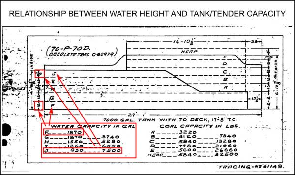
Motion pumps are something I touched on briefly in one proposal I had written about refining locomotive water systems.

Other topics discussed:
  • Specifying water system parameters instead of making assumptions based on boiler and cylinder data.
  • Potentially more realistic models for injectors (both live and exhaust steam).
  • Simulation of feedwater heater systems.
  • Specifying presence of Fusible Plugs.
  • Simulating low-water alarms
  • Allowing the tender water supply to deplete in a non-linear fashion. (Most water tanks are not a perfect cube/rectangular prism!)

Attached File(s)


#119 User is offline   darwins 

  • Superintendant
  • Group: Posts: Elite Member
  • Posts: 1,273
  • Joined: 25-September 17
  • Gender:Male
  • Simulator:Open Rails
  • Country:

Posted 28 May 2024 - 12:26 PM

Quote

Allowing the tender water supply to deplete in a non-linear fashion.


We do not see the water in the tender.

We do see the water level on a gauge connected to the tender or tank. As you say these are often non-linear.

They are not the only non-linear gauges that I have seen in locomotive cabs, nor are non-linear gauges peculiar to steam locos. I have seen non linear speed gauges, brake gauges and to some extent also steam pressure gauges.

Perhaps these could be specified with an input table in cvf files rather than just assuming that all dials and gauges have a linear relationship.

#120 User is online   Weter 

  • Member, Board of Directors
  • PipPipPipPipPipPipPipPipPipPip
  • Group: ET Admin
  • Posts: 7,437
  • Joined: 01-June 20
  • Gender:Not Telling
  • Simulator:ORTS
  • Country:

Posted 28 May 2024 - 07:49 PM

Hello.
By the way, yes: many gauges I remember (with spring-loaded mechanisms/sensors) have non-linear scales, more or less.
Currently, *.cvf-file asks only for scale's range and full length/arc.

  • 14 Pages +
  • « First
  • 10
  • 11
  • 12
  • 13
  • 14
  • You cannot start a new topic
  • You cannot reply to this topic

1 User(s) are reading this topic
0 members, 1 guests, 0 anonymous users