Elvas Tower: Steam Locomotive Additional Features - Elvas Tower

Jump to content

Posting Rules

All new threads will be started by members of the Open Rails team, Staff, and/or Admins. Existing threads started in other forums may get moved here when it makes sense to do so.

Once a thread is started any member may post replies to it.
  • 14 Pages +
  • « First
  • 8
  • 9
  • 10
  • 11
  • 12
  • Last »
  • You cannot start a new topic
  • You cannot reply to this topic

Steam Locomotive Additional Features Rate Topic: -----

#91 User is offline   Laci1959 

  • Foreman Of Engines
  • Group: Status: Contributing Member
  • Posts: 986
  • Joined: 01-March 15
  • Gender:Male
  • Simulator:Alföld
  • Country:

Posted 22 April 2024 - 11:45 AM

View Postdarwins, on 22 April 2024 - 11:24 AM, said:

That locomotive has only one engine. You should not use


That's for sure?
Then the devil took it away. It's a waste.
It would have been good because the rotation of the two front wheels is unrealistic when slipping. I thought this was a solution to a ten-year-old problem.

#92 User is offline   darwins 

  • Superintendant
  • Group: Status: Elite Member
  • Posts: 1,265
  • Joined: 25-September 17
  • Gender:Male
  • Simulator:Open Rails
  • Country:

Posted 22 April 2024 - 11:46 AM

https://i.imgur.com/9Rjssyn.jpeg

For this loco with only one engine 22.0 + 22.0 + 22.0 = 66.0 so we use

  ORTSDriveWheelWeight ( 66.0t-uk )


https://i.imgur.com/Tj06T98.jpeg

For this loco for the front engine 20.0 + 20.0 + 19.95 = 59.95 and for the rear engine 20.65 + 21.0 + 21.0 = 62.65 so we use
ORTSAdhesion (
  Wheelset (
 	Axle (
  	Weight ( 59.95t-uk )
      	)
 	Axle (
  	Weight ( 62.65t-uk )
      	) ) )


#93 User is offline   Traindude 

  • Engineer
  • Group: Status: Contributing Member
  • Posts: 698
  • Joined: 17-November 13
  • Gender:Male
  • Location:Seattle, WA
  • Simulator:Open Rails
  • Country:

Posted 29 April 2024 - 01:36 AM

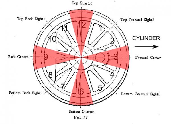
I touched on this a while back in a private convo with some of the big steam guys on this forum, but I think that it would be beneficial to map any steam exhaust emissions and sounds (pulse-based) to the crankpin position.

Here's what the exhaust pattern for a two- or four-cylinder (non-articulated/non-duplex) locomotive looks like...:
Attached Image: crankclock_2cyl.jpg

NOTE: The numbers on the driving wheel are to help people locate the crankpin positions by imagining the face of the wheel as a clock face. Sometimes it's more helpful than "Forward Dead Center", "Top Quarter", etc.

It could be possible to map the exhaust emissions and sound to the crankpins if the shape file's animation keyframes on which each crankpin hits a "dead center" is known. (For pre-existing models, you may have to uncompress the shape file to find this information.) Here's how it can potentially be coded into an *.eng file (two-cylinder with 16 driving wheel keyframes assumed):
ORTSWheelCrankAngleDifference ( 0deg 90deg )
ORTSWheelCrankDeadCenterKeyFrames(
Comment ( *** Left Cylinder *** ) 
    Cylinder1 ( 
        Forward ( 0 ) 
        Back ( 8 )
    )
Comment ( *** Right Cylinder *** ) 
    Cylinder2 (
        Forward ( 4 )  
        Back ( 12 )
    ) 
)


Here's what a four-cylinder locomotive (GWR Castle, Balanced Compound, etc.) would be coded (again, assuming there are 16 driving wheel keyframes total):
ORTSWheelCrankAngleDifference ( 0deg 180deg 270deg 90deg )
ORTSWheelCrankDeadCenterKeyFrames(
Comment ( *** Left Outer Cylinder *** ) 
    Cylinder1 ( 
        Forward ( 0 ) 
        Back ( 8 )
    )
Comment ( *** Left Inner Cylinder *** ) 
    Cylinder2 ( 
        Forward ( 8 ) 
        Back ( 0 )
    )
Comment ( *** Right Inner Cylinder *** ) 
    Cylinder3 (
        Forward ( 12 )  
        Back ( 4 )
    ) 
Comment ( *** Right Outer Cylinder *** ) 
    Cylinder4 (
        Forward ( 4 )  
        Back ( 12 )
    ) 
)


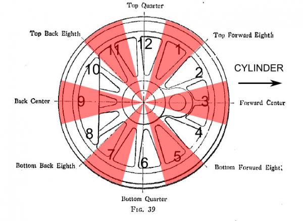
For 3-cylinder locomotives (Flying Scotsman, Union Pacific 9000), the exhaust pattern would look like this:
Attached Image: crankclock_3cyl.jpg

Even though there are 6 puffs/chuffs per driving wheel rotation, the driving wheel animation is still divided into 8 or 16 keyframes. Since 4 is not divisible by 3, it becomes necessary to specify non-integer values for the dead center keyframes (again, 16 keyframes assumed):
ORTSWheelCrankAngleDifference ( 0deg 120deg 240deg )
ORTSWheelCrankDeadCenterKeyFrames(
Comment ( *** Left Cylinder *** ) 
    Cylinder1 ( 
        Forward ( 0 ) 
        Back ( 8 )
    )
Comment ( *** Center Cylinder *** ) 
    Cylinder2 ( 
        Forward ( 2.667 ) 
        Back ( 10.667 )
    )
Comment ( *** Right Cylinder *** ) 
    Cylinder3 (
        Forward ( 5.33 )  
        Back ( 13.33 )
    ) 
)


In the case of articulated (Big Boy, Challenger, etc.) or divided-drive (PRR T1, Q2, etc.) locomotives, these parameters would fall within each ORTSSteamEngines grouping (one-piece model with 16 keyframes assumed):
ORTSSteamEngines ( 2
        Steam (
                Comment ( Front Steam Engine )
                NumCylinders ( 2 )
                CylinderStroke ( 32.0in )
                CylinderDiameter ( 23.0in )
                AttachedAxle( 0 )
                ExcessRodBalance ( 100lb )
                ORTSWheelCrankAngleDifference ( 0deg 90deg )
                ORTSWheelCrankDeadCenterKeyFrames(
                Comment ( *** Left Cylinder *** ) 
                    Cylinder1 ( 
                        Forward ( 0 ) 
                        Back ( 8 )
                     )
                Comment ( *** Right Cylinder *** ) 
                    Cylinder2 (
                        Forward ( 4 )  
                        Back ( 12 )
                    ) 
                )
              )
        Steam (
                Comment ( Rear Steam Engine )
                NumCylinders ( 2 )
                CylinderStroke ( 32.0in )
                CylinderDiameter ( 23.0in )
                AttachedAxle( 1 )
                ExcessRodBalance ( 100lb )
                ORTSWheelCrankAngleDifference ( 0deg 90deg )
                ORTSWheelCrankDeadCenterKeyFrames(
                Comment ( *** Left Cylinder *** ) 
                    Cylinder1 ( 
                        Forward ( 0 ) 
                        Back ( 8 )
                     )
                Comment ( *** Right Cylinder *** ) 
                    Cylinder2 (
                        Forward ( 4 )  
                        Back ( 12 )
                    ) 
                )
               )                
    )


For geared locomotives (Heisler, Shay, Climax), the gear reduction complicates the calculation of the dead centers, as these dead centers would be located relative to the crankshaft instead of the wheels, even though the wheels are animated "conventionally."

#94 User is offline   pschlik 

  • Conductor
  • Group: Status: Contributing Member
  • Posts: 417
  • Joined: 04-March 15
  • Gender:Male
  • Simulator:OpenRails - Unstable
  • Country:

Posted 24 May 2024 - 06:58 PM

Our local simulated hyacinth macaw's latest Derail Valley video covered a mod which changes the steam loco's throttle/steam chest behavior to what the steam expert considers significantly more accurate. Instead of the throttle setting a target pressure for the steam chest, the throttle controls the flow rate into the steam chest, which will eventually achieve boiler pressure regardless of how little the throttle is opened (assuming no steam is consumed). This changes the driving methodology as at low speeds the throttle cannot control tractive effort directly. In fact, most throttle settings will get the steam chest right up to full pressure unless the cylinder cocks are open to let steam out. Closing the throttle doesn't immediately reduce the steam chest pressure as the steam in there sticks around until it's consumed by the cylinders. At low speeds, most of the throttle is a deadzone where applying more throttle doesn't actually give more steam, but at high speeds the entire throttle is useful. Because the throttle controls flow rate, the average chest pressure at a given throttle and speed will depend on steam outflow, so lower cutoff settings give higher chest pressure as steam will be consumed slower. Lots of interesting stuff, more involved than "50% throttle = 50% chest pressure".

However, this can be compared to Open Rails, which is still using the old MSTS-level understanding (one of many many things MSTS got wrong that leeched into the 'common sense' of simmers despite being utterly wrong) of the throttle that the throttle directly sets the chest pressure instantly. It would be interesting for OR to simulate the more accurate, but more challenging, behavior. This would require some estimation though (how much steam flow does the throttle allow? what's the effective volume of the steam chest? if the locomotive is superheated, is the throttle before or after the superheater?) as I doubt every detail of the throttle response is well documented. Still, I'd like to see it done.

#95 User is offline   Traindude 

  • Engineer
  • Group: Status: Contributing Member
  • Posts: 698
  • Joined: 17-November 13
  • Gender:Male
  • Location:Seattle, WA
  • Simulator:Open Rails
  • Country:

Posted 24 May 2024 - 07:36 PM

View Postpschlik, on 24 May 2024 - 06:58 PM, said:

Our local simulated hyacinth macaw's latest Derail Valley video covered a mod which changes the steam loco's throttle/steam chest behavior to what the steam expert considers significantly more accurate. Instead of the throttle setting a target pressure for the steam chest, the throttle controls the flow rate into the steam chest, which will eventually achieve boiler pressure regardless of how little the throttle is opened (assuming no steam is consumed). This changes the driving methodology as at low speeds the throttle cannot control tractive effort directly. In fact, most throttle settings will get the steam chest right up to full pressure unless the cylinder cocks are open to let steam out. Closing the throttle doesn't immediately reduce the steam chest pressure as the steam in there sticks around until it's consumed by the cylinders. At low speeds, most of the throttle is a deadzone where applying more throttle doesn't actually give more steam, but at high speeds the entire throttle is useful. Because the throttle controls flow rate, the average chest pressure at a given throttle and speed will depend on steam outflow, so lower cutoff settings give higher chest pressure as steam will be consumed slower. Lots of interesting stuff, more involved than "50% throttle = 50% chest pressure".

However, this can be compared to Open Rails, which is still using the old MSTS-level understanding (one of many many things MSTS got wrong that leeched into the 'common sense' of simmers despite being utterly wrong) of the throttle that the throttle directly sets the chest pressure instantly. It would be interesting for OR to simulate the more accurate, but more challenging, behavior. This would require some estimation though (how much steam flow does the throttle allow? what's the effective volume of the steam chest? if the locomotive is superheated, is the throttle before or after the superheater?) as I doubt every detail of the throttle response is well documented. Still, I'd like to see it done.


I totally agree, and I've previously discussed this possibility of adding throttle response lag a few years ago.

Also, keep in mind that in the case of compound locomotives, any changes made to the throttle settings won't be reflected at the low-pressure cylinders until the driving wheels turn far enough to let the high-pressure cylinders exhaust some.

#96 User is offline   darwins 

  • Superintendant
  • Group: Status: Elite Member
  • Posts: 1,265
  • Joined: 25-September 17
  • Gender:Male
  • Simulator:Open Rails
  • Country:

Posted 24 May 2024 - 09:54 PM

It would certainly be good to see more accurate models of regulators.

For simple locomotives these came in two types -
The US "balanced regulator" and
The "twin port regulator" with a pilot valve and main port.

Some of the twin port regulators had different characteristics when opening and when closing - in which case if you really wanted to know the throttle setting you needed to fully close the regulator and then open it again!


Regulators for compounds could be more complicated. The Deeley regulator used on the three cylinder compounds common in UK admitted boiler steam directly to the low pressure cylinders for starting until it was opened more than half way. Above that the low pressure cylinders were cut off and steam was admitted directly to the high pressure cylinder. Once past this point steam was always routed to the high pressure cylinder whatever the regulator position until it was fully closed and then opened again.


Although Chapelon favoured the US type of balanced regulator for his compounds, there were various different starting arrangements possible. I am sure I have seen a cab picture with both a large and small regulator handle on the same axis!

#97 User is offline   Traindude 

  • Engineer
  • Group: Status: Contributing Member
  • Posts: 698
  • Joined: 17-November 13
  • Gender:Male
  • Location:Seattle, WA
  • Simulator:Open Rails
  • Country:

Posted 24 May 2024 - 11:01 PM

View Postdarwins, on 24 May 2024 - 09:54 PM, said:

It would certainly be good to see more accurate models of regulators.

For simple locomotives these came in two types -
The US "balanced regulator" and
The "twin port regulator" with a pilot valve and main port.

Some of the twin port regulators had different characteristics when opening and when closing - in which case if you really wanted to know the throttle setting you needed to fully close the regulator and then open it again!


Regulators for compounds could be more complicated. The Deeley regulator used on the three cylinder compounds common in UK admitted boiler steam directly to the low pressure cylinders for starting until it was opened more than half way. Above that the low pressure cylinders were cut off and steam was admitted directly to the high pressure cylinder. Once past this point steam was always routed to the high pressure cylinder whatever the regulator position until it was fully closed and then opened again.


Although Chapelon favoured the US type of balanced regulator for his compounds, there were various different starting arrangements possible. I am sure I have seen a cab picture with both a large and small regulator handle on the same axis!


Agreed. For latter-day North American steam locos, there's the American Multi-valve throttles (see attached literature), which were used universally from the late 1920s until the end of the North American steam era.

Attached File(s)


#98 User is offline   Weter 

  • Member, Board of Directors
  • PipPipPipPipPipPipPipPipPipPip
  • Group: ET Admin
  • Posts: 7,261
  • Joined: 01-June 20
  • Gender:Not Telling
  • Simulator:ORTS
  • Country:

Posted 25 May 2024 - 01:06 AM

Hello, Phillip.

Quote

hyacinth macaw
:good:
I suppose, this is totally right and true:

Quote

Instead of the throttle setting a target pressure for the steam chest, the throttle controls the flow rate into the steam chest, which will eventually achieve boiler pressure regardless of how little the throttle is opened (assuming no steam is consumed).

The pressure can be lower, but only if the flow after regulator will be greater, than through regulator's opening, all it's way further. See Bernoulli's law. (in short, the energy of heated steam are existing in three forms: pressure, speed and internal. Higher speed - lower pressure and vice-versa. In thinner openings, pressure turns into speed, in cameras (our chest, when no steam used) - speed is zero, so the pressure is maximal, internal energy is only being decreased, due to hydrawlic resistance of piping and due to cooling, but later I'll tell, how it can be utilized for useful work).
In other cases, the most "thinner opening" between boiler (maximal pressure's value, "full") and athmosphere (the "zero" pressure) will determine resulting pressure. Note, I've substituted "minimal" word to "zero", because inside thin opening itself, pressure will be less, than athmospheric - having the negative value. This causes ejection effect, which is known to be used for vacuum generation, e.g. for brakes in British-type railroad brakes.
So, I'd correct Your last conclusion (do You mind?): assuming less steam, than regulator currently passes, is being consumed.

Quote

At low speeds, most of the throttle is a deadzone where applying more throttle doesn't actually give more steam, but at high speeds the entire throttle is useful.

I think, this is to be wrong. And here is the cause of crazy wheelslip's possibility, once tractive effort exceeds adhesion - just open regulator a little more. It will form "deposite of energy" in chest, which will blow-oute, once slipping occurs.

I continue:

Quote

This changes the driving methodology as at low speeds the throttle cannot control tractive effort directly

Cutoff is intended for this. Generally, yes: biggest cutout means, the steam works in cylinders without expansion (i.e. freeing-out it's internal energy), but only by means of constant and almost equal steam chest's and cylinder's pressure (it will be passed by piston to crank, causind whell to turn). At low speeds, where inertia of rolling locomotive can't move pistons and valves all their travel long (whole wheel's turn), this is only the way for engine to complete it's working cycle. But in greater speeds, driver can reduce cut-out time, so portion of steam, locked in cylinder under higher pressure, can expand, utilising more of it's internal energy (pressure drops, internal energy is being used during expansion), and the process of expansion turns from isobaric to adiabatic (see these terms, if not familiaf - for physics details and formulae). See also
Hence,

Quote

In fact, most throttle settings will get the steam chest right up to full pressure unless the cylinder cocks are open to let steam out.

Yes and no: in case of movement takes place, steam usage in form of pulsation does take place.

Quote

Closing the throttle doesn't immediately reduce the steam chest pressure as the steam in there sticks around until it's consumed by the cylinders.

True, as well, as an opposite: regulator's opening doesn't cause immediate maximal effect: time needed for pressure in chest to grow-up. (my greetings to Sanjay)

Quote

Because the throttle controls flow rate, the average chest pressure at a given throttle and speed will depend on steam outflow, so lower cutoff settings give higher chest pressure as steam will be consumed slower.
Indeed!

wikipedia said:

greatest power is achieved by keeping the inlet valve open throughout the power stroke (thus having full boiler pressure, minus transmission losses, against the piston throughout the stroke) while peak efficiency is achieved by only having the inlet valve open for a short time and then letting the steam expand in the cylinder (expansive working)
The point at which steam stops being admitted to the cylinder is known as the cutoff, and the optimal position for this varies depending on the work being done and the tradeoff desired between power and efficiency. Steam engines are fitted with regulators (throttles in US parlance) to vary the restriction on steam flow, but controlling the power via the cutoff setting is generally preferable since it makes for more efficient use of boiler steam.


I'd add, that in local tradition, it was accepted to state, that superheating the steam have proven to bring same efficiency, than compound engines, but by more simple, light and perfect way, because it, in addition, have allowed to take more heat from fire and to make steam dryer. So, compound locomotive were cuccessed by simple superheated.

Quote

if the locomotive is superheated, is the throttle before or after the superheater?

I think, before: it's inside boiler (under the steam dome) and protects thin superheater's pipes from being under full boiler pressure all the time. There are some very good scanned books about steam locomotive's design, but they are not in English. However mr.Newell (a.k.a. steamer_ctn) have managed, how to read them.

#99 User is offline   Traindude 

  • Engineer
  • Group: Status: Contributing Member
  • Posts: 698
  • Joined: 17-November 13
  • Gender:Male
  • Location:Seattle, WA
  • Simulator:Open Rails
  • Country:

Posted 25 May 2024 - 02:41 AM

View PostWeter, on 25 May 2024 - 01:47 AM, said:

I think, before: it's inside boiler (under the steam dome) and protects thin superheater's pipes from being under full boiler pressure all the time. There are some very good scanned books about steam locomotive's design, but they are not in English. However mr.Newell (a.k.a. steamer_ctn) have managed, how to read them.


Not always. Many latter-day North American locomotives had the throttle after the superheater and before the cylinders. See my earlier document of the Multiple-Valve throttle.

#100 User is offline   Weter 

  • Member, Board of Directors
  • PipPipPipPipPipPipPipPipPipPip
  • Group: ET Admin
  • Posts: 7,261
  • Joined: 01-June 20
  • Gender:Not Telling
  • Simulator:ORTS
  • Country:

Posted 25 May 2024 - 02:48 AM

Hello.
Thanks. I actually guessed, while really didn't know all design variants. It's interesting discovery for me.

  • 14 Pages +
  • « First
  • 8
  • 9
  • 10
  • 11
  • 12
  • Last »
  • You cannot start a new topic
  • You cannot reply to this topic

1 User(s) are reading this topic
0 members, 1 guests, 0 anonymous users