Elvas Tower: Raildriver adoption - Elvas Tower

Jump to content

  • 6 Pages +
  • « First
  • 2
  • 3
  • 4
  • 5
  • 6
  • You cannot start a new topic
  • You cannot reply to this topic

Raildriver adoption Rate Topic: -----

#31 User is offline   R H Steele 

  • Executive Vice President
  • PipPipPipPipPipPipPipPipPip
  • Group: ET Admin
  • Posts: 3,447
  • Joined: 14-March 13
  • Gender:Male
  • Location:known universe
  • Simulator:Open Rails
  • Country:

Posted 07 February 2019 - 10:49 AM

View PostR H Steele, on 06 February 2019 - 07:20 PM, said:

RE: Calibrating RD

Every locomotive I've tried starts with 100% dynamics...anyone else??I found the dynamic brakes calibration a little confusing ( and I calibrated many times using Raildrivers calibration format) - but I'm going to assume I messed up the instructions...so going to go through it again.
Thanks again, perpetualkid, your efforts much appreciated.

It was me, not understanding the instructions. Now everything works, LOVE the fact that the bailout actually engages and disengages! My Auto Brake still is a little off, better than before, maybe I need to replace the unit.


#32 User is offline   perpetualKid 

  • Fireman
  • Group: Status: Active Member
  • Posts: 190
  • Joined: 10-June 18
  • Gender:Male
  • Simulator:OR
  • Country:

Posted 08 February 2019 - 08:07 AM

View PostR H Steele, on 07 February 2019 - 10:49 AM, said:

It was me, not understanding the instructions. Now everything works, LOVE the fact that the bailout actually engages and disengages! My Auto Brake still is a little off, better than before, maybe I need to replace the unit.


let me guess, you did calibration in order Full Throttle - Dynamic Setup - Dynamic Brake, while the calibration indeed is going from Full Throttle - Dynamic Brake and back to Dynamic Setup-
I think the former is more intuitive, however I followed the same pattern as the original calibration from PI, which is the latter sequence.

If there are ideas for improvement on the process or guidance, I'm open to implement further changes.

#33 User is offline   R H Steele 

  • Executive Vice President
  • PipPipPipPipPipPipPipPipPip
  • Group: ET Admin
  • Posts: 3,447
  • Joined: 14-March 13
  • Gender:Male
  • Location:known universe
  • Simulator:Open Rails
  • Country:

Posted 08 February 2019 - 07:25 PM

View PostperpetualKid, on 08 February 2019 - 08:07 AM, said:

let me guess, you did calibration in order Full Throttle - Dynamic Setup - Dynamic Brake, while the calibration indeed is going from Full Throttle - Dynamic Brake and back to Dynamic Setup-
I think the former is more intuitive, however I followed the same pattern as the original calibration from PI, which is the latter sequence.

If there are ideas for improvement on the process or guidance, I'm open to implement further changes.

I agree, the former is more intuitive, additionally shouldn't the "null" point ( Dynamic Brake Setup ) be set first and then Dynamic Brake....I'm in favor of changing it.Full Throttle - Dynamic Setup - Dynamic Brake
One other question, does this version of monogame permit the use of ReShade? I seem to be having difficulty in getting it working with this version, works fine with other monogame versions.
Thank you.


#34 User is offline   EricF 

  • Fireman
  • Group: Status: Active Member
  • Posts: 217
  • Joined: 07-December 11
  • Gender:Male
  • Location:New England
  • Simulator:Open Rails / Sometimes MSTS
  • Country:

Posted 09 February 2019 - 06:44 AM

I believe PI Engineering uses the sequence Full Throttle > Full Dynamic Brake > Dynamic Brake Setup to calculate the full range of the control and then derive the center region between the extreme end values.

Some (possibly) interesting thoughts:

I've seen the Rail Driver's circuit board, and apparently the analog controls (and, interestingly, the rotary controls as well) are capacitive, not resistive or magnetic Hall-effect potentiometers.
Variable capacitor controls have a little bit of lag as they charge and discharge when varying their output. While the RailDriver's analog-to-digital conversion for USB output might smooth that a bit, I suspect it's important to sample the output of the controls fairly rapidly and average the samples to get a good "read" on control positioning. (Too few samples will result in a strong "rubber-band" feel, and vague, drifting physical positioning of the levers in relation to the expected throttle "notch" regions and brake position values.)

What that means for calibration is, when the user lets go of the control and clicks the calibration button, take multiple samples and average, and wait for a bit (in milliseconds) for the average to settle into a reasonable tolerance before taking the calilbration snapshot. It shouldn't take but a few milliseconds, but a good, stable average and high enough sample rate is key.

Likewise, when reading movement to determine where the control is in relation to throttle notch points and braking percentages, you have to account for "input lag" as the control moves, the capacitance catches up, and the output stabilizes. A fast enough sample rate will help with that.

Why did PI use variable capacitor controls instead of the more common resistive potentiometers or Hall-effect potentiometers? My guess is they wanted to duplicate some of the "input lag" that's inherent in real locomotive controls. Real locomotive controls are linked through electrical relays and pneumatic systems. There's always a bit of delay between actuating a control and getting a response. The capacitive controls provide a little bit of baseline delay.

The challenge is handling it correctly in the software. Slow sample rates (or worse, just taking the first value from a single sample) will give the rubber-band effect and vague control positions. Faster sample rates will account for the "sluggish" change rates of the capacitive controls and make for more predictable behavior. There will always be a baseline delay to account for in calibration and operation.

One of these days, I really need to publish the pictures I took of the insides of the RailDriver on my blog... It's kind of intriguing, if you like knowing how things work.

#35 User is offline   jared2982 

  • Superintendant
  • Group: Status: First Class
  • Posts: 1,187
  • Joined: 01-January 10
  • Gender:Male
  • Location:Louisiana
  • Simulator:MSTS, TS2017, OR
  • Country:

Posted 09 February 2019 - 10:55 AM

Did some testing today and found a couple of issues. One- the sander will not turn off with the button on RD. I had to turn it off using the keyboard. The second issue is the horn. If I blow it with the RD pulling the switch down does nothing. Once I release the horn switch the horn starts to blow. Pulling the horn switch back down stops it until I release the switch and it starts blowing again. The only way to turn it off is to blow it using the keyboard. Everything else seemed to work just fine. The only thing I have is there needs to be a way to delete key assignments from the RD key map. If there is I could not find it.

Cheers

#36 User is offline   perpetualKid 

  • Fireman
  • Group: Status: Active Member
  • Posts: 190
  • Joined: 10-June 18
  • Gender:Male
  • Simulator:OR
  • Country:

Posted 10 February 2019 - 05:05 AM

Quote


View Postjared2982, on 09 February 2019 - 10:55 AM, said:

Did some testing today and found a couple of issues. One- the sander will not turn off with the button on RD. I had to turn it off using the keyboard. The second issue is the horn. If I blow it with the RD pulling the switch down does nothing. Once I release the horn switch the horn starts to blow. Pulling the horn switch back down stops it until I release the switch and it starts blowing again. The only way to turn it off is to blow it using the keyboard. Everything else seemed to work just fine. The only thing I have is there needs to be a way to delete key assignments from the RD key map. If there is I could not find it.

Cheers


thanks for the feedback, there's been an issue in the code affecting button presses which is now fixed in attached version.
As for deleting a key mapping, seems indeed a missing functionality I will look into (seems not even Keyboard key mapping has such functionality).

//removed attachment

#37 User is offline   perpetualKid 

  • Fireman
  • Group: Status: Active Member
  • Posts: 190
  • Joined: 10-June 18
  • Gender:Male
  • Simulator:OR
  • Country:

Posted 10 February 2019 - 05:15 AM

View PostEricF, on 09 February 2019 - 06:44 AM, said:

I believe PI Engineering uses the sequence Full Throttle > Full Dynamic Brake > Dynamic Brake Setup to calculate the full range of the control and then derive the center region between the extreme end values.

Some (possibly) interesting thoughts:


thanks EricF, this is really helpful input.
The RD driver samples input data in a ringbuffer, and one could either read all data in the buffer (and maybe run sliding averages on top), or skip ahead and read the last input only. Currently I've implemented the latter, reading at each frame, which should give a sampling frequency high enough for decent level of accuracy.
Still as they are analogous controls only, there is some variation and drift in the samplings, ie. influenced by temperature etc, so maybe worth to run calibration more often.
I also experienced now that Throttle idle position gives fairly different readings, whether moving the lever from full throttle, or from dynamic brake, into idle throttle position - I may add some extra handling to account for.


Looking forward to see your insights published somewhere!


#38 User is offline   EricF 

  • Fireman
  • Group: Status: Active Member
  • Posts: 217
  • Joined: 07-December 11
  • Gender:Male
  • Location:New England
  • Simulator:Open Rails / Sometimes MSTS
  • Country:

Posted 10 February 2019 - 10:54 AM

Using the frame rate as the reference for sampling frequency should work reasonably well, unless in testing you start to see the control response degrading under low or widely varying frame rates. Just keep in mind that the RailDriver's output must be scanned frequently enough to keep the Open Rails input buffer supplied with enough position information, and do so consistently. Buffer underrun and excessive variation will cause irregular input lag. Avoid that to keep from getting frustrated with irregular control reliability. To look at it another way, for reference, a basic computer mouse tends to output samples at 125 Hz or more, and software samples that stream at a lower rate to keep the input buffer full.


Part of the reason that lever position in relation to set points (like throttle neutral) varies so much is because the position-sensor components are all on a board at one end of the Rail Driver case. They're connected to the levers by long rotating linkages with tensioning springs to apply some "weight" and resistance to movement. So physical torque effects will cause the sensor to come to rest in a slightly different position depending on how fast in in what direction the control is moving before it stops. You may be able to compensate for that by allowing for a larger tolerance for each software-defined set point during calibration and/or operation. It may be aggravated by the slight delay as the capacitor output varies, too. Remember when you move a control and then stop, the output value may continue to rise or fall for a few milliseconds once you let go of the physical lever, so there needs to be an adequate sampling "window" in time to determine if the control has achieved a steady dwell state or not.

I actually came to computer technology from work and hobbies in analog electronics -- mostly radio and audio systems. I'm used to thinking in analog terms, so if you wonder if the RailDriver is doing anything funky, I might be able to figure out what's happening in analog terms and give you information you can relate to for programming around.

#39 User is offline   jared2982 

  • Superintendant
  • Group: Status: First Class
  • Posts: 1,187
  • Joined: 01-January 10
  • Gender:Male
  • Location:Louisiana
  • Simulator:MSTS, TS2017, OR
  • Country:

Posted 10 February 2019 - 08:12 PM

View PostperpetualKid, on 10 February 2019 - 05:05 AM, said:

thanks for the feedback, there's been an issue in the code affecting button presses which is now fixed in attached version.
As for deleting a key mapping, seems indeed a missing functionality I will look into (seems not even Keyboard key mapping has such functionality).

Attachment Program.zip


I tested the new update and things seem to have been improved when it comes to the horn and such. Still an issue with not being able to delete or unassign a key that is already mapped. An example would be the sand button. By default it is set up to activate and stay activated until you release the button. If you want to change it to sand toggle, press once and sand on, press again and sand off, it will not work correctly because it is already mapped to sand as describes previously.

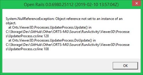
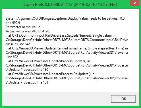
Also I received two errors while testing.
This is one that I receive each time I quit a route
Attached Image: ORMG error.jpg


This one I receive randomly while running the sim. It does not seem to be linked with the use of any certain feature of the RD or OR as far as I can tell.
Attached Image: ORMG error2.jpg

#40 User is offline   perpetualKid 

  • Fireman
  • Group: Status: Active Member
  • Posts: 190
  • Joined: 10-June 18
  • Gender:Male
  • Simulator:OR
  • Country:

Posted 10 February 2019 - 10:52 PM

View Postjared2982, on 10 February 2019 - 08:12 PM, said:

I tested the new update and things seem to have been improved when it comes to the horn and such. Still an issue with not being able to delete or unassign a key that is already mapped. An example would be the sand button. By default it is set up to activate and stay activated until you release the button. If you want to change it to sand toggle, press once and sand on, press again and sand off, it will not work correctly because it is already mapped to sand as describes previously.


I'm working to get key assignments removed, stay tuned.

View Postjared2982, on 10 February 2019 - 08:12 PM, said:

This one I receive randomly while running the sim. It does not seem to be linked with the use of any certain feature of the RD or OR as far as I can tell.
Attachment ORMG error2.jpg


this one is an interesting one, as it means the train has a negative speed - which I didn't assume to happen. Negative speed would indicate an negative direction, in which case it would be velocity instead. Speed is just distance over time, and wherever something moves, the distance is positive (in our part of the universe).
It will be simple to workaround, but something is conceptually wrong higher up in the simulation code...

  • 6 Pages +
  • « First
  • 2
  • 3
  • 4
  • 5
  • 6
  • You cannot start a new topic
  • You cannot reply to this topic

1 User(s) are reading this topic
0 members, 1 guests, 0 anonymous users