Elvas Tower: Additional Train Forces - Elvas Tower

Jump to content

Posting Rules

All new threads will be started by members of the Open Rails team, Staff, and/or Admins. Existing threads started in other forums may get moved here when it makes sense to do so.

Once a thread is started any member may post replies to it.
  • 8 Pages +
  • « First
  • 3
  • 4
  • 5
  • 6
  • 7
  • Last »
  • You cannot start a new topic
  • You cannot reply to this topic

Additional Train Forces Rate Topic: -----

#51 User is offline   Genma Saotome 

  • Owner Emeritus and Admin
  • PipPipPipPipPipPipPipPipPipPipPipPipPip
  • Group: ET Admin Group
  • Posts: 15,661
  • Joined: 11-January 04
  • Gender:Male
  • Location:United States
  • Simulator:Open Rails
  • Country:

Posted 26 August 2018 - 09:57 AM

Peter, many thanks for digging into this topic.

WRT r0(), a couple of questions:

  • If x is the position of the coupler at rest is it a safe assumption that is where the model shows the coupler -- hence a value of zero?
  • If y is the maximum travel allowed does the program treat it as a plus/minus range?


IIRC Damping() was used in MSTS to create a spring effect (sometimes people used values that created a too lively spring that would never settle down). Might you take a bit of time and experiment with that? It might be quite relevant to the larger train forces topic w/ specific regard to run-in forces.

Last, what's the purpose of Buffers() and is that used in OR??

#52 User is offline   steamer_ctn 

  • Open Rails Developer
  • Group: Posts: Elite Member
  • Posts: 1,980
  • Joined: 24-June 11
  • Gender:Male
  • Country:

Posted 26 August 2018 - 02:39 PM

View PostGenma Saotome, on 26 August 2018 - 09:57 AM, said:

If x is the position of the coupler at rest is it a safe assumption that is where the model shows the coupler -- hence a value of zero?
Setting x at zero is what I believe is the ideal setting. However it will depend upon how the modeller has defined the model in the size statement, etc. For example, depending upon the coupler type, it may need to extend beyond the wagon shape a bit.

So some experimentation will be required.


View PostGenma Saotome, on 26 August 2018 - 09:57 AM, said:

If y is the maximum travel allowed does the program treat it as a plus/minus range?
Yes.

The one challenge that I see, will be that the coupler does not actually move with slack movement (independent of the cars), and hence depending upon the current amount of slack, the couplers of two cars may either overlap, or have a gap between them.


View PostGenma Saotome, on 26 August 2018 - 09:57 AM, said:

IIRC Damping() was used in MSTS to create a spring effect (sometimes people used values that created a too lively spring that would never settle down). Might you take a bit of time and experiment with that? It might be quite relevant to the larger train forces topic w/ specific regard to run-in forces.
Currently the Damping parameter are not read and used by OR.

As far as doing any major changes to the coupling code, I am not inclined at this moment to do so, as I don't fully understand the logic used in it. I have attempted to seek clarification from the original developer to understand the model that they have defined, so we will see what happens.


View PostGenma Saotome, on 26 August 2018 - 09:57 AM, said:

Last, what's the purpose of Buffers() and is that used in OR??
Buffers were not used in MSTS (according to the MSTS Docs) and are not used in OR.

As I understand it, couplers have two states, ie tension (pulling) and compression (pushing). I would suspect that the behaviour would be different in each coupler state, and that the buffers would more influence the compression state. At the moment OR appears to treat both states the same, with one being a positive state and the other being a negative state.

#53 User is offline   Genma Saotome 

  • Owner Emeritus and Admin
  • PipPipPipPipPipPipPipPipPipPipPipPipPip
  • Group: ET Admin Group
  • Posts: 15,661
  • Joined: 11-January 04
  • Gender:Male
  • Location:United States
  • Simulator:Open Rails
  • Country:

Posted 26 August 2018 - 03:42 PM

View Poststeamer_ctn, on 23 August 2018 - 08:57 PM, said:

In Appendix A of this document are some examples of typical Coupler Forces.


This fails to open correctly for me (I see pages 1 and 2 but the rest never display).

#54 User is offline   mbm_OR 

  • Conductor
  • Group: Posts: Active Member
  • Posts: 263
  • Joined: 03-July 15
  • Gender:Male
  • Location:Spain
  • Simulator:Open Rails
  • Country:

Posted 30 August 2018 - 06:42 AM

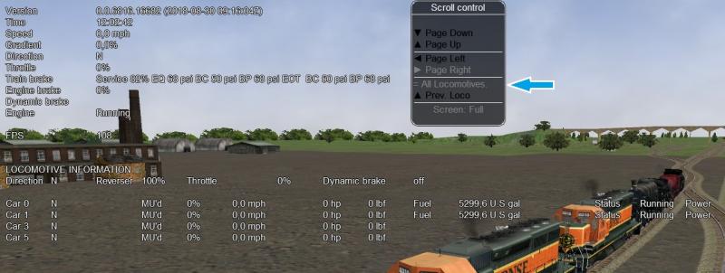
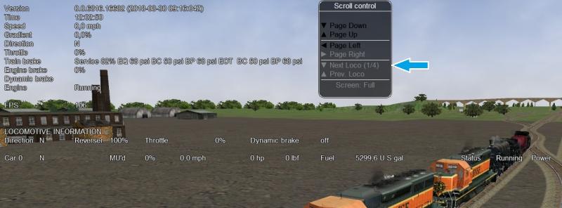
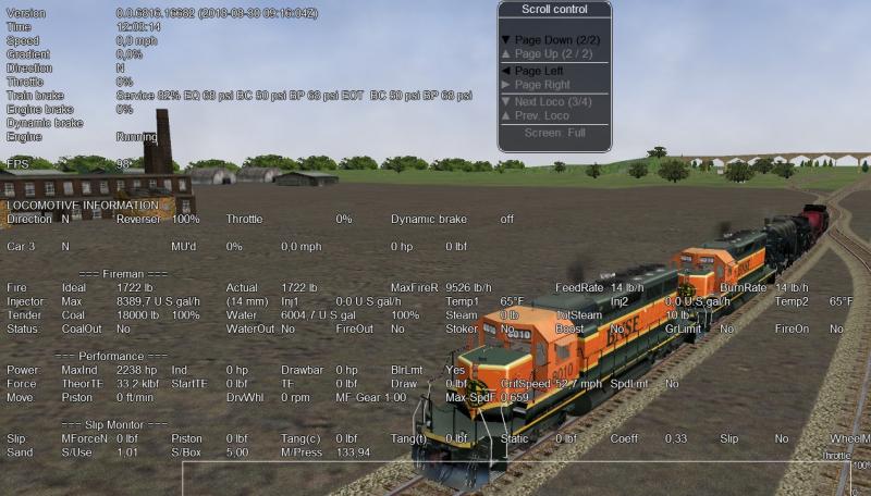
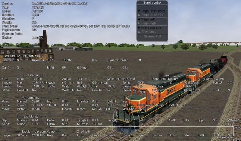
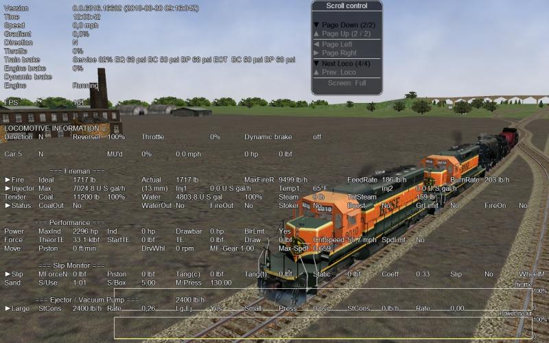
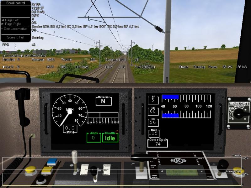
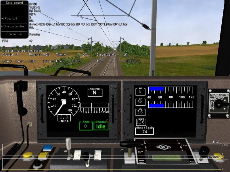
Now Locomotive information is ready.
About, Brake Information, it remains a job in progress.

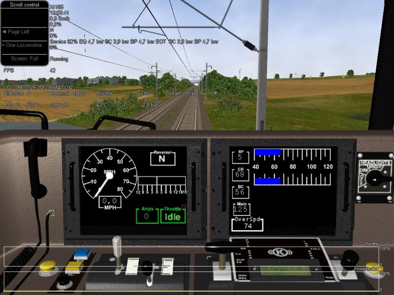
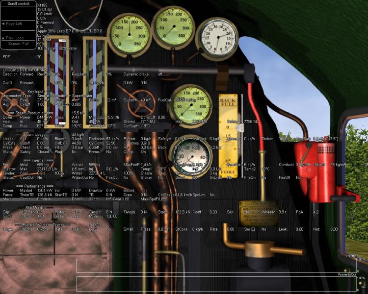
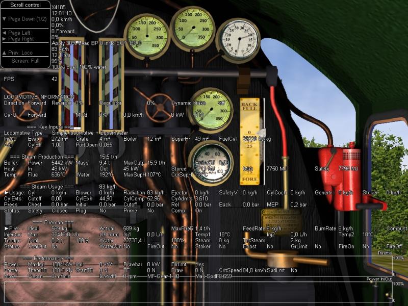
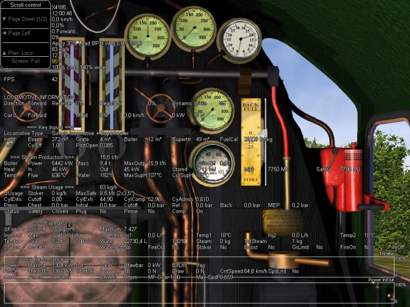
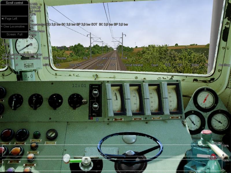
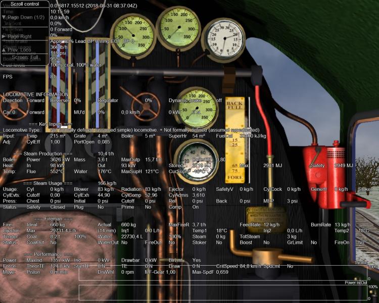
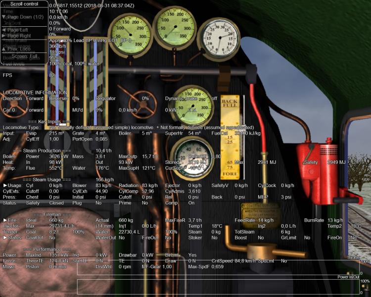
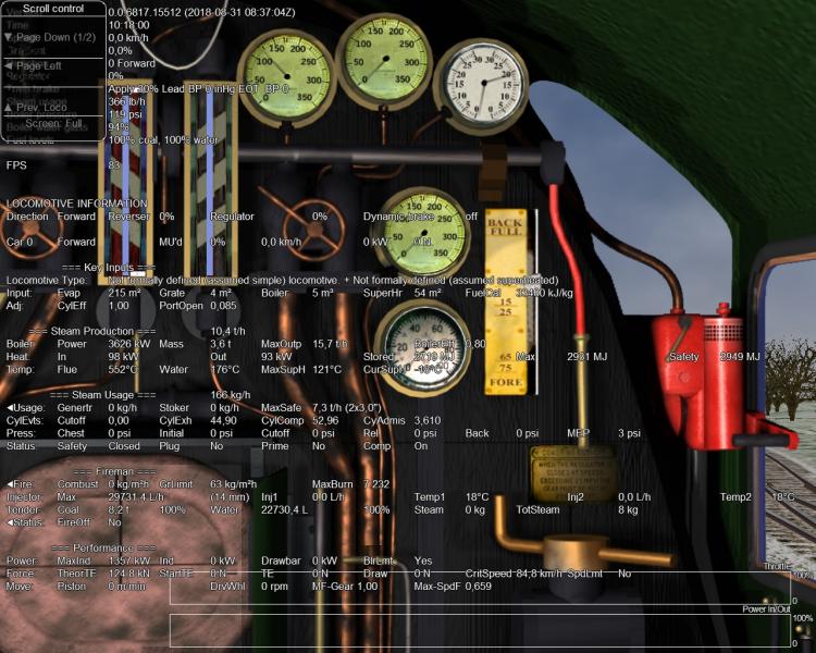
Some screenshots about Locomotive information:
All locomotives.
Attached Image: 01-Open Rails All Locomotives.jpg
Diesel loco.
Attached Image: 02-Open Rails Next Loco.jpg
Steam loco Car 3.
Attached Image: 03-Open Rails Car 3 Loco Page 2.jpg
Steam loco Car 5.
Attached Image: 04-Open Rails Last Loco Page 2.jpg
Page right scroll.
Attached Image: 05-Open Rails Car 5 Loco Page 2 Page Right.jpg

Attached test file for x4185.
31/08/2018. Deleted, by new code.

Regards,
Mauricio.

#55 User is offline   Genma Saotome 

  • Owner Emeritus and Admin
  • PipPipPipPipPipPipPipPipPipPipPipPipPip
  • Group: ET Admin Group
  • Posts: 15,661
  • Joined: 11-January 04
  • Gender:Male
  • Location:United States
  • Simulator:Open Rails
  • Country:

Posted 30 August 2018 - 09:04 AM

I tried V4185 a few minutes ago, a simple test on level ground of a reverse movement to take up the slack, around 60 cars. I allowed the locomotives to move for about 5 seconds and then throttled down.

What I noticed was the coupler force bounced from zero to 12k fpds (a bit more than 16kN) on some cars; most were around 7-8k fpds (9.5kN - 10,kN) and back again on all cars. I watched this for about 2 minutes and there was an almost imperceptible movement back and forth in the cars for the entire time.

From a game performance issue there were a lot of unnecessary calculations going on as the train speed was zero. I suppose at zero speed extra calculations are a don't care. From a user point of view it's very likely to also be a non-issue (assuming your r0() values are tight)... it you don't look carefully you won't notice the cars moving back and forth. OTOH, if your r0() values are not tight (e.g. cushioned underframe cars) the back and forth could be very noticeable.

From a physics point of view, clearly the damping function isn't there (we all knew this beforehand).

Obviously real railroad cars do stop... the question I suppose then is this: Is there a simple, temporary solution that can be implemented until such time Damping() is properly figured out and coded? Something effectively akin to a calculus limit, perhaps tied to low speed, perhaps tied to low force?

Q: Does positive rolling resistance have an effect upon push-in coupler forces? Does it take into account the effect of no slack in the attached car(s) located in the direction of the push?

#56 User is offline   hroch 

  • Fireman
  • Group: Posts: Active Member
  • Posts: 203
  • Joined: 05-June 14
  • Gender:Male
  • Simulator:MSTS OR
  • Country:

Posted 31 August 2018 - 02:06 AM

Mauricio

about locomotive information:
When the 1280x1024 resolution at the diesel locomotive is not displayed value of flow.
normal screen
Attached Image: normal1280x1024.jpg

page right
Attached Image: locomotive_information_moving_right_1280x1024.jpg

When the 1024x768 resolution at the diesel locomotive is not displayed value of load
normal screen
Attached Image: normal1024x768.jpg
page right
Attached Image: locomotive_information_moving_right_1024x768.jpg

When resolution is 1280x1024 at the steam locomotive does not move the line at a fire.
Attached Image: normal_steam1280x1024.jpg

When resolution is 1024x768 at the steam locomotive does not move the line at a Status and is not displayed value of Combust.
normal screen
Attached Image: steam_1024x768_normal.jpg
page right
Attached Image: steam_1024x768_moving_right.jpg

When resolution is 1024x768 at the electric locomotive does not work move.
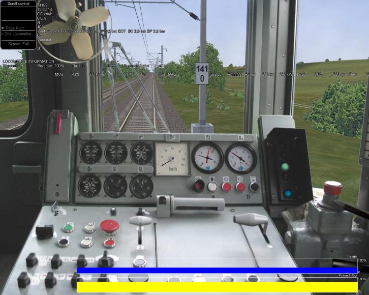
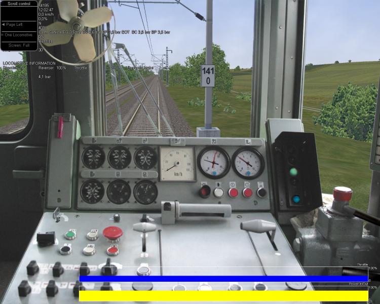
page right
Attached Image: eltrickal_1024x768.jpg

#57 User is offline   mbm_OR 

  • Conductor
  • Group: Posts: Active Member
  • Posts: 263
  • Joined: 03-July 15
  • Gender:Male
  • Location:Spain
  • Simulator:Open Rails
  • Country:

Posted 31 August 2018 - 11:00 AM

Thanks for your detailed feedback.

View Posthroch, on 31 August 2018 - 02:06 AM, said:

When the 1280x1024 resolution at the diesel locomotive is not displayed value of flow.

Please, try the attached new code.

View Posthroch, on 31 August 2018 - 02:06 AM, said:

When resolution is 1280x1024 at the steam locomotive does not move the line at a fire.

I have noticed that with the same display resolution, there are different amounts of data displayed.
In the steam locomotive information, there are more sections displayed in your screenshots.
Normal:
Attached Image: 1280x1024-Steam-normal.jpg

First page right:
Attached Image: 1280x1024-Steam-First-Right.jpg

Second page right:
Attached Image: 1280x1024-Steam-Second-Right.jpg


Maybe, the font text used is different. I need to take a look.

Attached test file for x4185.

19/10/2018. Deleted, by new code.

#58 User is offline   steamer_ctn 

  • Open Rails Developer
  • Group: Posts: Elite Member
  • Posts: 1,980
  • Joined: 24-June 11
  • Gender:Male
  • Country:

Posted 31 August 2018 - 10:24 PM

View Postmbm_OR, on 31 August 2018 - 11:00 AM, said:

I have noticed that with the same display resolution, there are different amounts of data displayed.
In the steam locomotive information, there are more sections displayed in your screenshots.
Depending upon the type of steam locomotive some additional data might be displayed.

For example, a compound locomotive will have two lines of steam cylinder pressures, ie the high and low cylinder pressure, whereas for a simple locomotive normally on one line of information is displayed.

View PostGenma Saotome, on 30 August 2018 - 09:04 AM, said:

Q: Does positive rolling resistance have an effect upon push-in coupler forces? Does it take into account the effect of no slack in the attached car(s) located in the direction of the push?

I am not 100% sure what is meant by the question, however I think the answer is yes to both questions.

#59 User is offline   mbm_OR 

  • Conductor
  • Group: Posts: Active Member
  • Posts: 263
  • Joined: 03-July 15
  • Gender:Male
  • Location:Spain
  • Simulator:Open Rails
  • Country:

Posted 01 September 2018 - 12:16 AM

View Poststeamer_ctn, on 31 August 2018 - 10:24 PM, said:

Depending upon the type of steam locomotive some additional data might be displayed.

Thanks Peter.
That is already taken into account by the code. The different steam locomotive data it's taken from the current Getstatus() code. The steam locomotive data are only formatted, not modified, by lines and columns according to the selected display resolution.

But, if we compare the same steam locomotive, with the identical screen resolution, the information, which fits on the hroch screenshots and mine, is different.
I suppose it could be an issue related to the type of text font used.

Regards,
Mauricio

#60 User is offline   Coolhand101 

  • Foreman Of Engines
  • Group: Posts: Contributing Member
  • Posts: 998
  • Joined: 13-June 15
  • Gender:Male
  • Simulator:MSTS
  • Country:

Posted 05 September 2018 - 03:57 AM

View Poststeamer_ctn, on 09 August 2018 - 12:14 AM, said:

With OR release #4168, wind resistance has been added.


I have just updated OR to x4185.

Using this feature, my EMU trains struggle to get pass 75mph on the level. The level balancing speed is 82mph. I have notice that the wind resistance is very high on certain coaches, namely the motor coaches. All the coaches have the same size but slightly difference mass.

My default EMU consist has this setup:

ENG+ENG+WAG+ENG.

If i use this test setup using the same mass and size as my default consist:

ENG+WAG+WAG+WAG

My EMU can get to 81-83mph on the level, depending on the wind strength and direction.

It appears the wind resistance is greatly enhanced if the consist has more than one engine, irrespectively of their size parameters.

Obviously these are my initial findings, so would the "ORTSWagonFrontalArea" and "ORTSDavisDragConstant" for my default consist that uses more than one engine, make the performance on par to my test consist?

I cannot seem to find any example setups on these two wind resistance parameters!

Thanks

#61 User is offline   steamer_ctn 

  • Open Rails Developer
  • Group: Posts: Elite Member
  • Posts: 1,980
  • Joined: 24-June 11
  • Gender:Male
  • Country:

Posted 05 September 2018 - 10:50 PM

View PostCoolhand101, on 05 September 2018 - 03:57 AM, said:

Using this feature, my EMU trains struggle to get pass 75mph on the level. The level balancing speed is 82mph.

What is meant by this?

The "balancing speed" with wind resistance may be higher or lower then the STILL air value depending upon the wind direction and speed.

So depending upon the wind present in OR this could be a reasonable outcome.

View PostCoolhand101, on 05 September 2018 - 03:57 AM, said:


It appears the wind resistance is greatly enhanced if the consist has more than one engine, irrespectively of their size parameters.

The wind resistance calculations are consistent with the STILL air resistance (or Friction value in the HUD), and reflect the STILL air resistance values used.

I am not sure of the methodology used for calculating the resistance of the locomotive in your consist, however let's assume that a default drag coefficient is used for the DavisC variable in the WAG file. Typically the original Davis equations suggested a drag coefficient value of 0.0024 for a locomotive. Whereas by comparison the freight and passenger cars are assigned values of 0.0005 and 0.00034 respectively. Hence their STILL air values are typically a lot lower at higher speeds compared to a locomotive, and the Wind resistance will be similar, as it is based upon the same constant.

So once the Davis values have been defined in an ENG file, these values are then used whenever the locomotive is placed in the consist, regardless of its location.

A possible clue exists in the definition of the Davis equations where multiple unit trains had the first car with a drag coefficient of 0.0024, and subsequent cars with drag coefficients of 0.00034. And to a certain extent this makes sense as drag would be more pronounced on the leading car as it "breaks wind", whereas trailing cars would not experience the same level of drag.

Based on your testing a single engine seems to work fine as it is "correctly" setup up for resistance, whereas multiple locomotives may not, as they reproduce drag for a leading vehicle where they are in fact trailing vehicles.

So the real question that perhaps needs to be asked is, "Is it true that the drag coefficient is the same regardless of where the locomotive is located in the consist?"

If the answer is no, and the air drag varies depending upon whether the car (engine) is leading or trailing, then additional OR coding, and configuration would be required. It would be necessary to define a locomotive with two resistance conditions, a leading, and a trailing, so extra physics parameters would be required in the ENG file.

So perhaps some scholarly research is required to answer the above question.

Thanks

#62 User is offline   Coolhand101 

  • Foreman Of Engines
  • Group: Posts: Contributing Member
  • Posts: 998
  • Joined: 13-June 15
  • Gender:Male
  • Simulator:MSTS
  • Country:

Posted 06 September 2018 - 12:22 AM

Thanks for the detailed reply Peter.

The EMU in question really has one engine for power, the other engines are driving trailers with no power :

Driving Trailer coach(ENG) = 35t
Engine coach(ENG) = 49t
Trailer coach(WAG) = 31t
Driving Trailer coach(ENG) = 35t

All have Davis parameters to enable a level balancing speed of 82 mph with still air.

With wind resistance on, i get around 75mph on the level. The wind resistance on the engine coaches vary between 100 to 450 ibs at 75mph. The Wag coach resistance varies between 7 and 35 ibs at 75 mph.

The test consist :

Driving Trailer coach(ENG) = 35t
Engine coach(WAG) = 49t
Trailer coach(WAG) = 31t
Driving Trailer coach(WAG) = 35t

All have Davis parameters to enable a level balancing speed of 82 mph with still air.

With wind resistance on, i get around 80 to 81 mph.

The wind resistance on the Engine coach varies between 125 to 475 ibs at 81 mph. The Wag coach resistance varies between 9 and 40 ibs at 81 mph.

So swapping the ENG coaches for WAG coaches produces this huge difference in wind resistance, yet they have the same size, mass and davis parameters.

If this is indeed correct. What would be the best approach?

For over 10 years from MSTS to OR, i have used different friction/davis parameters for consists that have more than one power coach. This allows a higher level balancing speed to simulate the extra power coaches applied against wind resistance. IE

4 car EMU = 82mph
8 car EMU = 84mph
12car EMU = 85mph.

In order to achieve these speeds with wind resistance enabled, would i have to change my original Davis parameters on the motor coaches or use the new Wind resistance parameters? For the latter, can you provide an example on how these parameters are setup?

Thanks

#63 User is offline   hroch 

  • Fireman
  • Group: Posts: Active Member
  • Posts: 203
  • Joined: 05-June 14
  • Gender:Male
  • Simulator:MSTS OR
  • Country:

Posted 06 September 2018 - 12:51 AM

Mauricio

When the 1024x768 resolution at the diesel locomotive is not displayed second value of power
normal screen
Attached Image: normal1024x768_06.jpg
page right
Attached Image: page_right_1024x768_06.jpg
Attached File  OpenRailsLog.txt (17.48K)
Number of downloads: 463
Everything other ( steam, electric ) works the same as in the patch 05.

#64 User is offline   steamer_ctn 

  • Open Rails Developer
  • Group: Posts: Elite Member
  • Posts: 1,980
  • Joined: 24-June 11
  • Gender:Male
  • Country:

Posted 06 September 2018 - 01:04 AM

View PostCoolhand101, on 06 September 2018 - 12:22 AM, said:

If this is indeed correct. What would be the best approach?
For me to comment any more then my earlier post I would need to look at the rolling stock and consist files for the two trains in question.

If you package them up and send them to me I will have a closer look, and see if I can give you any more feedback.

Thanks

#65 User is offline   Coolhand101 

  • Foreman Of Engines
  • Group: Posts: Contributing Member
  • Posts: 998
  • Joined: 13-June 15
  • Gender:Male
  • Simulator:MSTS
  • Country:

Posted 06 September 2018 - 03:33 AM

View Poststeamer_ctn, on 06 September 2018 - 01:04 AM, said:

For me to comment any more then my earlier post I would need to look at the rolling stock and consist files for the two trains in question.

If you package them up and send them to me I will have a closer look, and see if I can give you any more feedback.

Thanks


It happens with any wagon coach replaced with an engine coach in a consist.

For a common test ground, the Default MSTS SERIES7000 EMU can be use with the same results.

This consist is made up of two ENG coaches and nine WAG coaches. Replace some or all of the WAG coaches with ENG coaches using the same parameters from the WAG coaches but zero power. I have already made some examples here:

Attached File  series7000-test.zip (1.46K)
Number of downloads: 444


From this observation, you can see the wind resistance differences between ENG and WAG coaches, using the same dimensions as below :-

Wag coaches -

http://www.atomic-album.co.uk/showPic.php/178898/Open%20Rails%202018-09-06%2012-10-48.jpg


Engine coaches ( but different wind direction )-

http://www.atomic-album.co.uk/showPic.php/178898/Open%20Rails%202018-09-06%2012-21-14.jpg


Thanks

  • 8 Pages +
  • « First
  • 3
  • 4
  • 5
  • 6
  • 7
  • Last »
  • You cannot start a new topic
  • You cannot reply to this topic

1 User(s) are reading this topic
0 members, 1 guests, 0 anonymous users