Log In
 Register Now!
 Help
Help


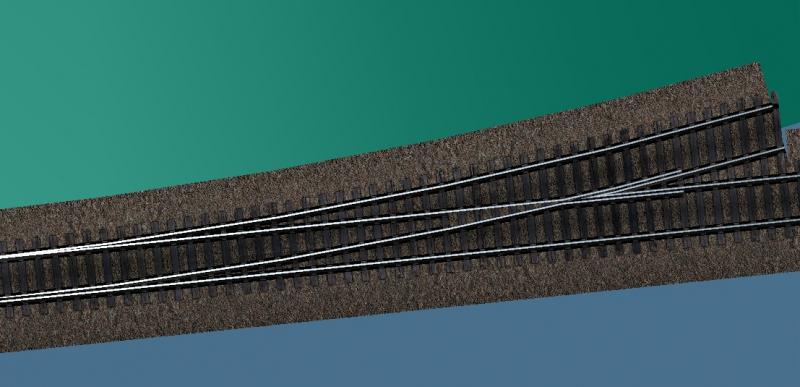
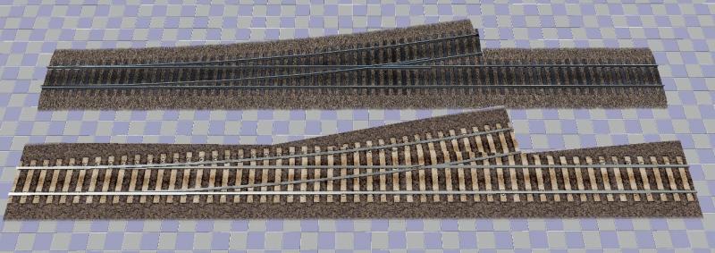
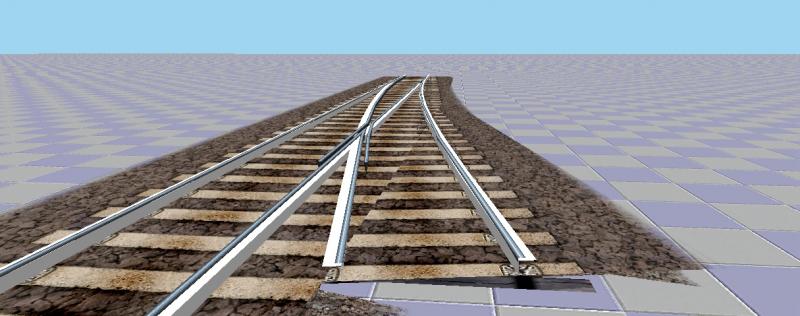
So building switches is actually not that hard, it's just time-consuming. I have completed a prototype:
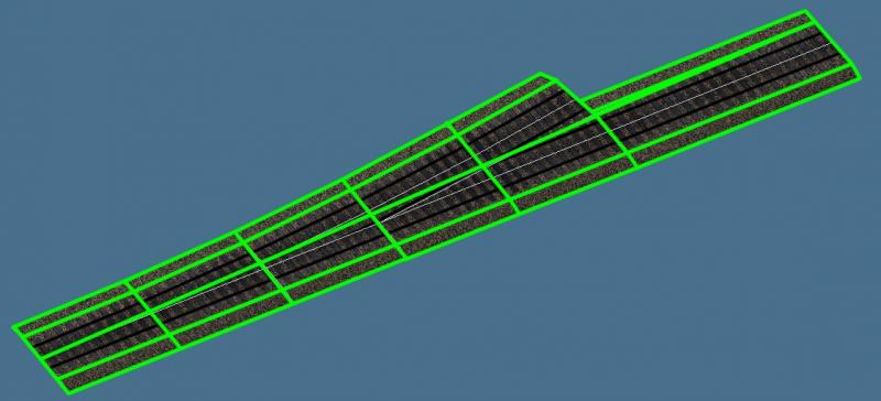
This shot gives an idea of how I built the ballast:
The steps are as follows:
- Create a cylinder with a height of zero, two cap sections, a radius set to match the curve, as many sides as it takes to match the number of curve sections you want (in this case, the cylinder has 180 sides, meaning there is a segment for every 2 degrees of arc) and placed a full radius to the side of the track center.
- Copy the straight section. Detach the ballast. Slice it along the centerline. Make sure you are in E-Poly as E-mesh will slice along face edges and create unnecessary vertices.
- In this new ballast section, use vertex snap to create several vertices at the points on the cylinder. Go one point past the desired end of the track. Move them to the centerline.
- Slice the ballast at the position of each vertex. You can delete those vertices now.
- Make sure the cylinder is at the same height as the top of the ballast. Grab the center vertex for each cross section and snap it to the edges of the circle. DO NOT ROTATE. Again, remember to go one point past the desired endpoint of the track.
- Position a slice plane at the centerline vertex that defines the desired endpoint of the track. Rotate it the correct number of degrees - in this case, 10.
- Slice the ballast layer. Delete anything past the endpoint. There will be a triangular segment from the original perpendicular edge on the inside of the curve, so snap those verts to the end, weld the UV coordinates with target weld in Unwrap UVW, and then weld the vertices in the mesh.
- Select the vertices defining the cross-section at the start of the track. Hold shift and drag to clone them. Rotate them the appropriate number of degrees for the end (in this case, 10 degrees).
- Grab the center vertex and snap it to the center of the end. You'll notice the ballast is a bit narrower at the end than it should be. Snap the edges of the mesh to these vertices. Remove isolated vertices.
- The curve is now correct and the ties will remain straight, ensuring overall alignment with the straight section.
- Detach the ballast from the straight section. Hide everything but the two ballast sections.
- On the ballast section, use edge cut to slice in the area where the two ballast sections will meet. It doesn't have to be perfect, just make sure it's between the rail and the end of the ties. Do this all the way down the section. At the start point of the curve, the last cut should be close to the center. Delete anything inside this new series of edges.
- Select the straight ballast layer. Use vertex snap and create vertices at those same new edge points. Slice plane across the ballast at those points.
- Use edge cut and vertex snap to cut the same edges. Delete everything on the curved side of those edges.
- Attach the curved section to the straight section. Weld the vertices where they meet.
The prototype piece is a little messier than I would do a final piece because I had sliced down the center, thinking it would make life easier (it did not, because I ended up edge cutting anyway):
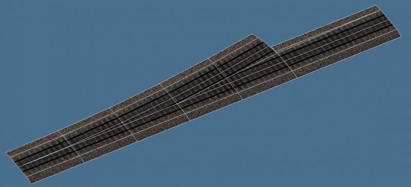
Ideally, future sections would look more like this:
I constructed the rails the same way, but this leads to a sight narrowing of the gauge from simply shifting left/right, so I would create them the same way I would build curves for the final version:
- Calculate the total length of the arc in meters. Divide by 24 to figure out the number of times the texture should repeat, round to the nearest half.
- Add a UVW XForm modifier. Enter this number in the V Tile field.
- Decide how many segments this curve needs. One segment per degree is probably best, so a curve that has 20 degrees of arc should have 20 segments.
- Position the end of the track at whatever that number is in meters, so for a 20 degree arc, place it 20 meters out.
- Slice every meter.
- Create the reference cylinder as with the ballast, make sure it has a number of sides that matches the number of segments - if there's to be a segment for every degree, there should be 360 sides. Make sure the cylinder has a height of 0 meters and is placed 0 meters above the origin.
- Select all vertices along one side of the ballast. Shift and drag to clone. Position them at the centerline.
- Snap each sequential segment to the points on the reference cylinder.
- Select each cross section and type in the number of degrees it should be rotated. In this example, there would be a segment for every degree of arc, so each segment should be rotated one more degree than the last.
For switches, the very last step would be to add an Unwap UVW modifier and move the coordinates for each cross-section vertically along the texture to get the tie plates lines up with the ties. This is a pretty simple matter.
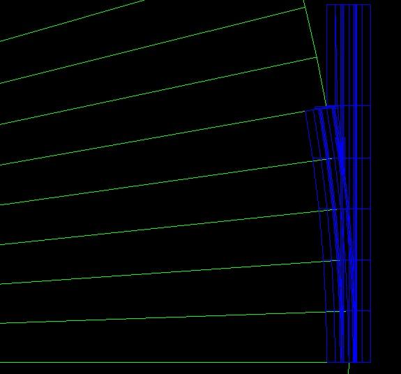
What isn't so simple is getting the placement and radius of the curves right. Here is my 10 degree test switch with the switch it was intended to match:
You can see that the curve is not positioned correctly. If I move it 1.5 meters down the track, it lines up well:
The inner rail matches fine when you consider the accidental narrowing of the gauge from the technique that was used. The outer rail, however, is nowhere close:
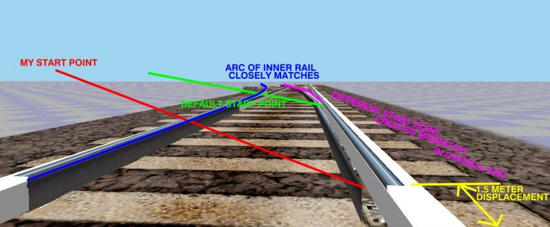
I used the numbers from the XTracks site for the radius, so that I'm sure of. Was the outer rail on the default shape just wrong? The slight (3 cm or so) narrowing of the gauge doesn't account for this huge difference on the position of the point of the curved moving segment.
Route developers: Do any of you have any input on the correct positioning of the start of the curve of the default switches? I suspect it's primarily a function of an opposing curve of the same radius and arc that meets a parallel track section, which would make calculations a simple matter of the radius, arc, and distance between tracks. That doesn't solve the outside rail misalignment problem, though. Whose outside rail is correct, theirs or mine?