Elvas Tower: HUD Visibility of Engine Brake - Elvas Tower

Jump to content

  • 3 Pages +
  • 1
  • 2
  • 3
  • You cannot start a new topic
  • You cannot reply to this topic

HUD Visibility of Engine Brake Rate Topic: -----

#21 User is offline   copperpen 

  • Executive Vice President
  • Group: Status: Elite Member
  • Posts: 3,144
  • Joined: 08-August 05
  • Gender:Male
  • Simulator:MSTS & OR
  • Country:

Posted 20 March 2016 - 01:29 AM

 steamer_ctn, on 19 March 2016 - 01:58 PM, said:


As has been agreed (?) by most participants there appears to be a need to differentiate between the pressures applied to the train brake and the engine brakes.


OK. I see why you have a running position on the engine brake now, but that diagram also shows a triple valve isolating cock in the engine brake system so it can operate in a more normal straight airbrake way.

"Running - In this position, the locomotive and tender brakes are "slaved" to the train brake system, so that if the train brakes are applied or released, the engine and tender brakes will go to the same state. This is the normal operating position for the engine and tender brakes".

This means that either you did not fully release the engine brake before applying the running position or we have a bug in the brake code somewhere. That still does not require a BC figure on the engine brake line, just a percentage of the application as it is now. It would appear that using the running position does not show this percentage like it does on brake systems that do not have a "running" position so it is doubtful that having a BC figure there will show either. Comparing your screen shot with a US style engine brake, the Running has actually replaced the application percentage figure that normally shows there.

It therefore looks like the train brake should be divorced from the engine brake in the HUD, and the engine brake display needs to be modified to show either released, running or applied but only needs to retain the percentage, not change it to a BC figure because a % figure tells you that you still have engine brakes applied to some degree.

#22 User is offline   steamer_ctn 

  • Open Rails Developer
  • Group: Status: Elite Member
  • Posts: 1,889
  • Joined: 24-June 11
  • Gender:Male
  • Country:

Posted 20 March 2016 - 09:03 PM

 copperpen, on 20 March 2016 - 01:29 AM, said:

This means that either you did not fully release the engine brake before applying the running position or we have a bug in the brake code somewhere.

I agree that OR does not currently appear to model all the different brake control valves.

For example, to maintain a particular pressure setting on the brake system that I modeled requires it to be set to the "Running" position, which as you correctly point out should slave it off the train brake. Ideally it should be held in the "Lap" position once a pressure is set on the brake, but the running position is the only position that stops the BC from increasing or decreasing.


 copperpen, on 20 March 2016 - 01:29 AM, said:

but only needs to retain the percentage, not change it to a BC figure because a % figure tells you that you still have engine brakes applied to some degree.

The percentage figure shown in the HUD is the position of the brake valve controller.

So whilst the percentage figure for a two position brake valve (ie graduated On/Off), such as on a Dash9 may appear to give an indication of the current BC value in a percentage figure, other locomotives with multiple position brake control valves will not be as clearly defined. For example the Golsdorf 380 appears to have a three position brake valve, which when operated shows % values for each of the three positions. These values do not appear to correspond to the actual value of the pressure in the BC.

To monitor the amount of engine brake application requires visibility of the BC value.

#23 User is offline   copperpen 

  • Executive Vice President
  • Group: Status: Elite Member
  • Posts: 3,144
  • Joined: 08-August 05
  • Gender:Male
  • Simulator:MSTS & OR
  • Country:

Posted 21 March 2016 - 02:20 AM

The Golsdorf 380 has a very peculiar brake setup with a long release section, a short lap section and an apply section. During the lap section, the engine brake is progressively applied to a max of 17psi. After that no more pressure is applied even when in the apply section of the handle movement.

The application of the engine brake and related BC pressure is a direct correlation of the brake handle position in the apply mode. 0% apply is 0BC, 100% apply is full BC whatever that may be. So, if the brakes are set up to give full release at the release point of the handle before moving back into running position there is still no need for engine brake BC to be displayed. I suspect that possibly your brake setup is working like the golsdorf and giving a partial engine brake application in the running position.

#24 User is offline   copperpen 

  • Executive Vice President
  • Group: Status: Elite Member
  • Posts: 3,144
  • Joined: 08-August 05
  • Gender:Male
  • Simulator:MSTS & OR
  • Country:

Posted 21 March 2016 - 04:12 AM

After further fiddling with the brake system supplied with the AU_ctn Hall class locomotive ( or_adv ) eng file, I can confirm that moving the engine brake from apply to running does not give full release and never will. The BC remaining will depend on what settings are used in the engine brake controller section. You have to move the controller to release before moving back to Running.

Notch( 0.0 0 TrainBrakesControllerFullQuickReleaseStart )
Notch( 0.01 0 TrainBrakesControllerRunningStart )
Notch( 0.05 1 TrainBrakesControllerGraduatedSelfLapStart )
Notch( 0.95 0 TrainBrakesControllerFullServiceStart )
Notch( 1.0 0 TrainBrakesControllerEmergencyStart )

This set up gives me a smooth graduated action for brake application. For notched applications you need to add in dummy notches between the Lap and service positions. Without those you go from zero to full in one shot when using a notched controller. This notched action may be desirable in a switch engine.

Moving back from Lap or Start to Running leaves a residual amount of air in the brake cylinders, the BC will be at whatever your Lap position is, 0.25 leaves 25% brake application in place. This percentage is visible when in any position after Running. It is not displayed in Running or Release position

#25 User is offline   steamer_ctn 

  • Open Rails Developer
  • Group: Status: Elite Member
  • Posts: 1,889
  • Joined: 24-June 11
  • Gender:Male
  • Country:

Posted 21 March 2016 - 10:31 PM

 copperpen, on 21 March 2016 - 04:12 AM, said:

Notch( 0.0 0 TrainBrakesControllerFullQuickReleaseStart )
Notch( 0.01 0 TrainBrakesControllerRunningStart )
Notch( 0.05 1 TrainBrakesControllerGraduatedSelfLapStart )
Notch( 0.95 0 TrainBrakesControllerFullServiceStart )
Notch( 1.0 0 TrainBrakesControllerEmergencyStart )

This set up gives me a smooth graduated action for brake application. For notched applications you need to add in dummy notches between the Lap and service positions.

Yes you are correct that the brake control valve using the above settings now works as smooth graduated application, which requires the player to continuously press the brake key to apply and release it. The continuous graduated application appears to be more suited to an electric brake control system rather then a notched pneumatic system.

For the discrete notched type of brake being modeled, to apply or release the engine brake, the driver would move the brake controller between different notches to allow the pressure in the BC to vary. They would not have to continuously press the apply or release key. So the suggested brake controller doesn't appear to represent the operation of the A6-ET brake controller being modeled.

If as suggested the brake controller provided can be modified by insertion of dummy notches to achieve the desired A6-ET operation, are you able to provide a coding example to match the desired operation?

I am still uncertain as to why it necessary to use the brake valve controller setting as the indication of how much engine brake application has been applied. Especially, as the HUD percentage value currently being used is a secondary data value (ie the brake control valve position) compared to the BC which is the primary data value, and in addition, it appears that not all the brake controller states can provide a meaningful control position indication (and hence brake application values).

Thanks

#26 User is offline   atsf37l 

  • Executive Vice President
  • Group: Status: First Class
  • Posts: 4,648
  • Joined: 25-February 05
  • Gender:Male
  • Location:San Diego
  • Simulator:ORTS
  • Country:

Posted 21 March 2016 - 11:28 PM

 Genma Saotome, on 19 March 2016 - 03:58 PM, said:

Yes.

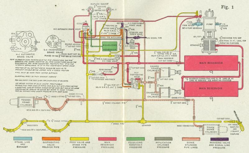
What seems tricky tho is what Herb has been nudging into the conversation: Apply the Automatic brake and watch the BC on ALL UNITS apply. Hit the bail off and the locomotive brake cylinders will vent to the atmosphere w/ apparently no effect anywhere else. Release the automatic brake to return everything to normal... now hit the Independent Brake. The locomotive's brake cylinders take on pressure and apply the locomotive brakes. No effect anywhere else. Straight air... apparently no triple valve here. Apply the automatic brake... all down the train line cylinders kick into action. Here is where it is not clear to me: if the Automatic brake is applied to a greater extent that the Independent, will the effect creep into the locomotives brake system? I think so but I do not understand how given the locomotive does not have a triple valve.

Herb? Help.

Yes it does and overrides the pressure in the cylinders, as I understand it. How it does that I do not know. As I said before, it's all in the way things are plumbed. It has to do with the distributing valve and the plumbing between the train brake controller and the independent brake valve. Once the distributing valve gets wind that there is an increase in train braking (a reduction which leads to an increase) that leads to a corresponding increase in the loco and tender brake cylinders.

Have fun looking this over. Try not to get lost.....
Attached Image: Westinghouse_Air_Brake_piping_diagram.jpg

#27 User is offline   atsf37l 

  • Executive Vice President
  • Group: Status: First Class
  • Posts: 4,648
  • Joined: 25-February 05
  • Gender:Male
  • Location:San Diego
  • Simulator:ORTS
  • Country:

Posted 22 March 2016 - 12:09 AM

Let me take it all a step further by sharing with you this 1911 Westinghouse Air Brake Equipment Manual.
Attached File  Air Brake Manuals.zip (12.34MB)
Number of downloads: 229

Pay particular attention to the section starting on page 359 of the manual describing the E. T. brake system most common to modern steam locomotives. As you read that section you will no doubt realize that our simulated brakes don't work quite the way the prototype does. :bigboss:

#28 User is offline   copperpen 

  • Executive Vice President
  • Group: Status: Elite Member
  • Posts: 3,144
  • Joined: 08-August 05
  • Gender:Male
  • Simulator:MSTS & OR
  • Country:

Posted 22 March 2016 - 06:45 AM

 steamer_ctn, on 21 March 2016 - 10:31 PM, said:


For the discrete notched type of brake being modeled, to apply or release the engine brake, the driver would move the brake controller between different notches to allow the pressure in the BC to vary. They would not have to continuously press the apply or release key. So the suggested brake controller doesn't appear to represent the operation of the A6-ET brake controller being modeled.

If as suggested the brake controller provided can be modified by insertion of dummy notches to achieve the desired A6-ET operation, are you able to provide a coding example to match the desired operation?

I am still uncertain as to why it necessary to use the brake valve controller setting as the indication of how much engine brake application has been applied. Especially, as the HUD percentage value currently being used is a secondary data value (ie the brake control valve position) compared to the BC which is the primary data value, and in addition, it appears that not all the brake controller states can provide a meaningful control position indication (and hence brake application values).

Thanks


This brake setup gives a number of notches between running and full application.

Brake_Engine ( 0 1 0.01 0.0
NumNotches ( 10
Notch( 0.0 0 TrainBrakesControllerFullQuickReleaseStart )
Notch( 0.01 0 TrainBrakesControllerRunningStart )
Notch( 0.10 0 Dummy )
Notch( 0.25 0 Dummy )
Notch( 0.40 0 Dummy )
Notch( 0.55 0 Dummy )
Notch( 0.70 0 Dummy )
Notch( 0.80 0 Dummy )
Notch( 0.95 0 TrainBrakesControllerFullServiceStart )
Notch( 1.0 0 TrainBrakesControllerEmergencyStart )

Each notch after the Running position will show a percentage of the engine brake applied. As ever, to fully release the brake you have to go to the release position before moving back to Running, exactly the same as the Train Brake system. The difference between engine and train brake is that the engine does not use the triple valve so release is fast. The Running position of both engine and train brake is somewhat similar to the Hold or Lap which require a move to the release position to release the brakes

  • 3 Pages +
  • 1
  • 2
  • 3
  • You cannot start a new topic
  • You cannot reply to this topic

1 User(s) are reading this topic
0 members, 1 guests, 0 anonymous users