 Log In
 Register Now!
 Help
Help
?
Page 1 of 1
Dynamic shadows are not cast when u,v coordinates have negative values? OR(v0.6.2)
if you use 3D Crafter/Canvas you may want to read this
Rate Topic:

#1

- Superintendant
-

- Group: Posts: Elite Member
- Posts: 1,025
- Joined: 31-May 10
- Gender:Male
-
Country:

Posted 13 September 2011 - 09:00 PM
#2
- Chairman, Board of Directors
-

- Group: ET Admin Group
- Posts: 13,931
- Joined: 21-February 06
- Gender:Male
- Location:Way, way, way, South
- Simulator:MSTS & OR
-
Country:

Posted 14 September 2011 - 03:55 AM
Nice detective work, Eldorado.
Cheers Bazza
Cheers Bazza
#3

- Open Rails Developer
-
- Group: Posts: Elite Member
- Posts: 5,514
- Joined: 30-June 10
- Gender:Not Telling
- Simulator:Open Rails
-
Country:

Posted 14 September 2011 - 09:47 AM
 Eldorado.Railroad, on 13 September 2011 - 09:00 PM, said:
1) OR seems to display models and their dynamic shadows correctly for wagons and locomotives that have been exported from 3D Canvas, even if the u,v numbers are not in the 0 to 1 range. Why is this? What preprocessing is going on here?
One of the options you can configure in a shape (for each primitive, I think) is what you do with out-of-bounds UV data. The options are wrap, mirror, clamp and border. These are pretty standard options, and are directly supported in hardware by graphics cards (meaning OR doesn't edit the UV data). I wouldn't be surprised if the exported data has used wrap or mirror, both of which shift all values outside 0-1 equally in to that range. Clamp and border don't shift them in the same way.
Eldorado.Railroad, on 13 September 2011 - 09:00 PM, said:
2) Why does OR not display a dynamic shadow if the item is not a locomotive or wagon and has u,v numbers that are not in the 0 to 1 range?
The shadow rendering, for performance, was written as a much simpler shader and set of code; one of the (many) things it doesn't support is this wrap/mirror/clamp/border option. For most of the options - such as the lighting (darkshade, etc.) - it doesn't matter for the shadows, but this particular one does, as you've notice. I will look to address this in a future update.
#4
- Owner Emeritus and Admin
-
- Group: ET Admin Group
- Posts: 15,661
- Joined: 11-January 04
- Gender:Male
- Location:United States
- Simulator:Open Rails
-
Country:

Posted 14 September 2011 - 11:43 AM
James Ross, on 14 September 2011 - 09:47 AM, said:
One of the options you can configure in a shape (for each primitive, I think) is what you do with out-of-bounds UV data. The options are wrap, mirror, clamp and border.
James, where in the .s file is that option set? I'd like to experiment a bit.
#5
- Open Rails Developer
-
- Group: Posts: Elite Member
- Posts: 5,514
- Joined: 30-June 10
- Gender:Not Telling
- Simulator:Open Rails
-
Country:
Posted 14 September 2011 - 12:23 PM
Genma Saotome, on 14 September 2011 - 11:43 AM, said:
James, where in the .s file is that option set? I'd like to experiment a bit.
That's a good question... let me dig through the code.
Okay it's from here: shape > light_model_cfgs > light_model_cfg > uv_ops > uv_op_copy. That contains two integers, one of which is called by OR "TexAddrMode". I don't know which because I don't have the source to Reader.dll. It has four possible values: 1 (wrap), 2 (mirror), 3 (clamp) and 4 (border).
#6
- Owner Emeritus and Admin
-
- Group: ET Admin Group
- Posts: 15,661
- Joined: 11-January 04
- Gender:Male
- Location:United States
- Simulator:Open Rails
-
Country:
Posted 15 September 2011 - 08:00 PM
James Ross, on 14 September 2011 - 12:23 PM, said:
That's a good question... let me dig through the code.
Okay it's from here: shape > light_model_cfgs > light_model_cfg > uv_ops > uv_op_copy. That contains two integers, one of which is called by OR "TexAddrMode". I don't know which because I don't have the source to Reader.dll. It has four possible values: 1 (wrap), 2 (mirror), 3 (clamp) and 4 (border).
Okay it's from here: shape > light_model_cfgs > light_model_cfg > uv_ops > uv_op_copy. That contains two integers, one of which is called by OR "TexAddrMode". I don't know which because I don't have the source to Reader.dll. It has four possible values: 1 (wrap), 2 (mirror), 3 (clamp) and 4 (border).
I created a cube with a patterned texture and edited copies to have a model w/ each value. MSTS RE was reluctant to display any of them -- they'd pop in and out of being visual depending on where the camera was. Anyway, value 3 was distinctly different looking than the others, the texture was definitely stretched across the polys as-if I had specified it to be huge relative to the size of the cube, but it was not obvious to me as to what rules it was using. 1 and 2 looked as I expected them to look (1 looks like the image of the texture file). Value 4 showed a tiny bit of the texture near one corner and in RE was black elsewhere, in OR simply missing. Weird. Here's the image I took in OR:
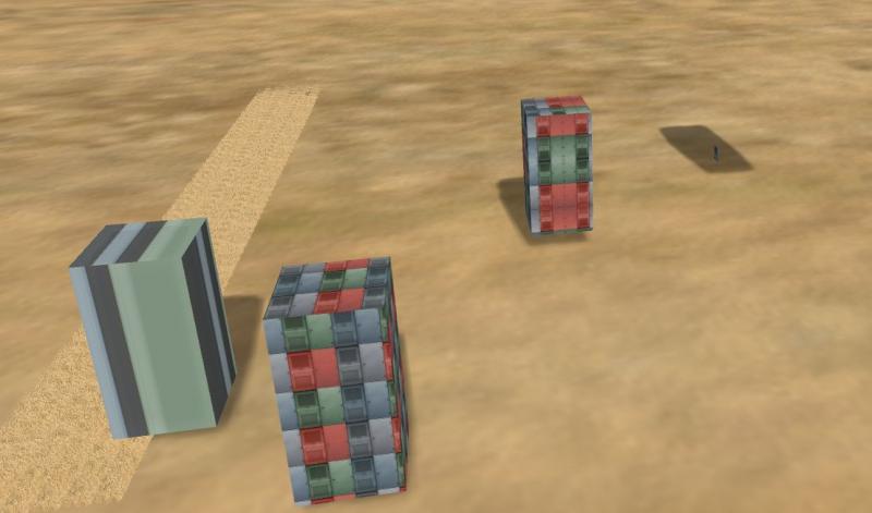
Left to right are values 3, 1, 2, 4
#7
- Owner Emeritus and Admin
-
- Group: ET Admin Group
- Posts: 15,661
- Joined: 11-January 04
- Gender:Male
- Location:United States
- Simulator:Open Rails
-
Country:
Posted 16 September 2011 - 09:54 AM
Sketchup -- but note that it is the .s file I edited, not the cad file.
The shadows are due to my copy, paste, edit of another shape in the .w file, one that had shadows turned on.
The shadows are due to my copy, paste, edit of another shape in the .w file, one that had shadows turned on.
#8
- Owner Emeritus and Admin
-
- Group: ET Admin Group
- Posts: 15,661
- Joined: 11-January 04
- Gender:Male
- Location:United States
- Simulator:Open Rails
-
Country:
Posted 16 September 2011 - 05:54 PM
You mean these?
Plenty of negative uv_points. I sized the texture to be a different size than the surface of the poly and then shoved the texture past the edge of most polys, all to see what effect there would be from the different control values James suggested.
	points ( 8
		point ( 0.0 10.0 0.0 )
		point ( 0.0 10.0 5.0 )
		point ( 5.0 10.0 0.0 )
		point ( 5.0 10.0 5.0 )
		point ( 5.0 0.0 0.0 )
		point ( 0.0 0.0 0.0 )
		point ( 0.0 0.0 5.0 )
		point ( 5.0 0.0 5.0 )
	)
	uv_points ( 19
		uv_point ( 0.0 -0.0 )
		uv_point ( 0.0 -1.25 )
		uv_point ( 1.25 -0.0 )
		uv_point ( 1.25 -1.25 )
		uv_point ( 1.570279 -0.427223 )
		uv_point ( 0.320279 -0.427223 )
		uv_point ( 1.570279 -2.927223 )
		uv_point ( 0.320279 -2.927223 )
		uv_point ( 0.330697 -2.126752 )
		uv_point ( 0.330697 0.373247 )
		uv_point ( -0.919302 -2.126752 )
		uv_point ( -0.919302 0.373247 )
		uv_point ( -1.25 -0.0 )
		uv_point ( 0.0 -2.5 )
		uv_point ( -1.25 -2.5 )
		uv_point ( -0.408876 -0.323303 )
		uv_point ( -0.408876 -2.823303 )
		uv_point ( 0.841123 -0.323303 )
		uv_point ( 0.841123 -2.823303 )
	)
Plenty of negative uv_points. I sized the texture to be a different size than the surface of the poly and then shoved the texture past the edge of most polys, all to see what effect there would be from the different control values James suggested.
Page 1 of 1