How to fix a mesh that does not have mapping coordinates and appears gray when a texture is applied.
Section 1. Freeform method of creating the Chassis
This will show you an alternate method of creating shapes with GMAX. It is recommended that you try both methods. You decide which one you prefer to use. The same principals apply to all shapes that you create.
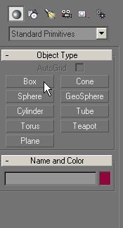
You choose Standard Primitives and the object type Box.
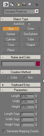
The create box options appears.
The parameter values:should all read 1.
The checkbox Generate Mapping Coordinates should also be checked.
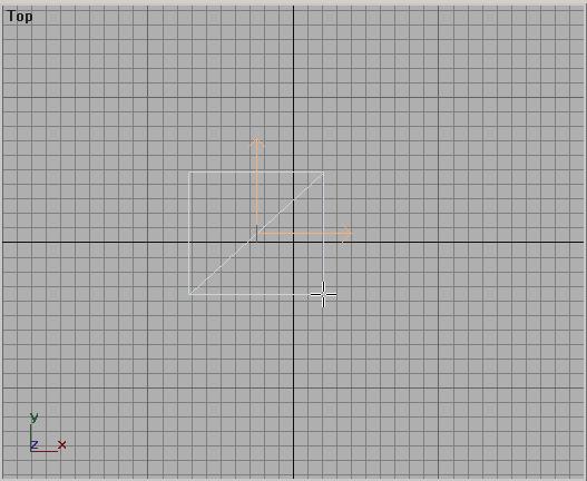
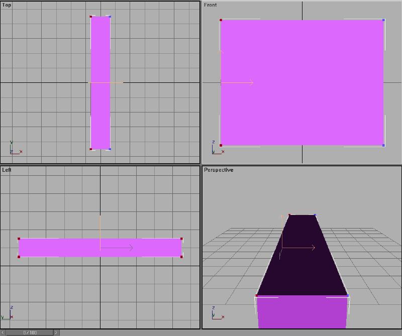
You will use the Top viewport. The mouse pointer changed its shape into a double cross. To make the Box, you place the cursor into the upper left region of the viewport, press and hold the left mouse button, draw the mouse to the lower right section of the viewport and release the mouse button. The result should look like this:
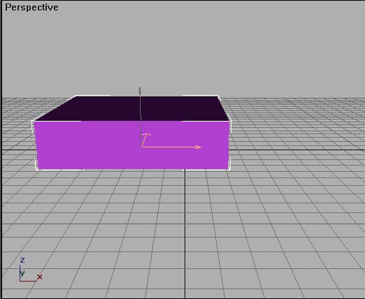
Now, you watch the Perspective Viewport, as the mouse moves, the box is getting its third dimension. You want the box to extend above the plane, not below. When the box seems high enough, you click again and our Box has been created. The colors of the objects are randomly chosen by Gmax, so yours may not be the same.
In the Top, Front and Left viewport you see a wireframe view of the box, and in the perspective viewport you see a solid model. You now want to switch the Top, Front and Left viewport to show solid models. To do this, you right-click onto the Viewport Names. Change each to Smooth + Highlights and the solid model will appear in the Viewport.
You now have to convert the object to an Editable Mesh in order the change its shape. To do this, you right-click on the shape. This brings up the Quad Menu.
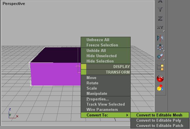
Select Convert to Editable Mesh. Your screen will switch from the Create panel to the Modify panel.
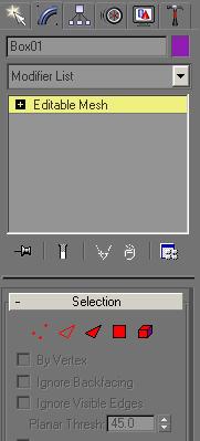
This screen will become very familiar to you as you continue to use GMAX. This is where your actual modeling of the different shapes takes place.
To avoid confusion and to stay in parallel with the main tutorial, rename Box01 to Chassis01.
The box you have created is nothing like the shape of the chassis you want. You will use the Modify panel (as the GMAX documentation refers the these screens) to modify the selected object to the size and shape that want.
You change to the Vertex mode:
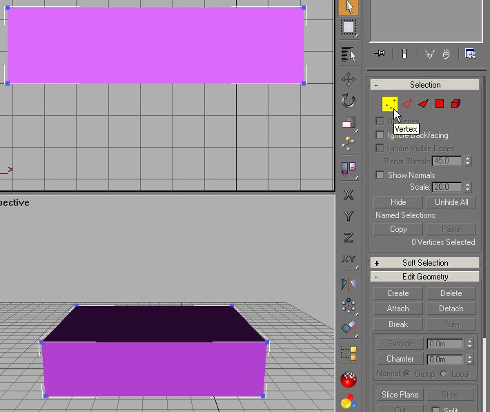
The vertices appear colored blue. Using the Select tool
![]() , draw a box
around the entire box in any one of the viewports. The selected vertices
will turn red when you release the mouse button. In this case; all the
vertices are selected.
, draw a box
around the entire box in any one of the viewports. The selected vertices
will turn red when you release the mouse button. In this case; all the
vertices are selected.
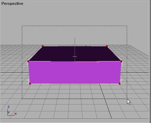
Using the Move tool
![]() you
position the box in the center of each of the viewports by placing your cursor
over one of the selected vertices. Your cursor will change to the Move
tool symbol. When you see this, click and hold the mouse button to move
the selected vertices. The positioning at this point is not ultra
critical, you are working with "in the ballpark" positioning.
Your result should appear something like this:
you
position the box in the center of each of the viewports by placing your cursor
over one of the selected vertices. Your cursor will change to the Move
tool symbol. When you see this, click and hold the mouse button to move
the selected vertices. The positioning at this point is not ultra
critical, you are working with "in the ballpark" positioning.
Your result should appear something like this:
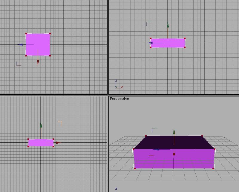
While constructing a loco or wagon for MSTS, the Left viewport shows the loco from the left as expected. The Top viewport shows the loco from the top of the screen.
The Front viewport actually shows the Back of the loco.
The chassis, you will convert your box to, has a length (Y-direction) of 9 meters, a width (X-direction) of 1.3 Meters and a height (Z-direction) of 1 meter. The chassis is centered in the virtual world system and hovers in a height of 0.5 meter above zero, which will place it above the rails in MSTS.
You should still have the Move tool selected. In the Left Viewport, click anywhere in the Viewport to make that Viewport active and at the same time, unselect all the vertices.
Draw a box to select the upper pair of vertices in the Left Viewport. You will see in the other viewports that you have selected the 4 vertices on the top of the box.
To move these vertices to their proper positioning in the GMAX world, you open the Move Transform Type-In dialog box. This is opened by moving your cursor over the highlighted Move tool, on the toolbar and right-clicking the mouse.
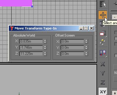 You want the top of the box positioned at 1.5m above the 0 line in the GMAX
world. The bottom will be 0.5m above the 0 line of the GMAX world and the
actual box will be 1.0 m high.
You want the top of the box positioned at 1.5m above the 0 line in the GMAX
world. The bottom will be 0.5m above the 0 line of the GMAX world and the
actual box will be 1.0 m high.
Enter 1.5 into the Z value in the Absolute World section and hit enter.
You do not need to enter the m, this is added automatically.
You see the box shape change in the viewports as soon as you hit the enter key.
You do not need to close the Move Transform Type-In dialog box
Now select the lower vertices in the Left Viewport and enter 0.5 into the Z value in the Absolute World section and hit Enter
The objects have probably become too small for you to see any spaces between the vertices in the Left Viewport. Don't worry about this yet. You are finished using the Left Viewport at this time. The next changes you will make will be using the Top Viewport.
Activate the Top Viewport. This deselects all selected vertices. You want our Chassis to be 9m long. You select the bottom vertices (the front) and enter a value of -4.5 in the Y value in the Absolute World section and hit Enter. Select the top vertices and enter a value of 4.5 into the Y value and hit enter.
Things are getting smaller and it is probably hard to see your shape in any Viewport, but don't panic or worry. You now move on the the Front Viewport.
Activate the Front Viewport and select the vertices on the right. Enter a value of 0.65 into the X value and hit Enter. Now select the vertices on the left and enter a value of -0.65 into the X value and hit enter.
Now seeing your shape is impossible in any viewport. This is easy to correct.
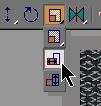
In the lower right corner of the GMAX screen, click on the
Zoom Extents All symbol.
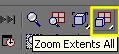
You will probably have to do this 2 or 3 times to get all views maximized. If you like to use keyboard shortcuts, Shift-Ctrl-Z.
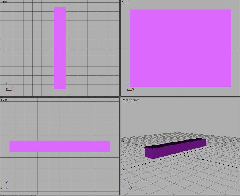
You should see your screen transform from something like this:
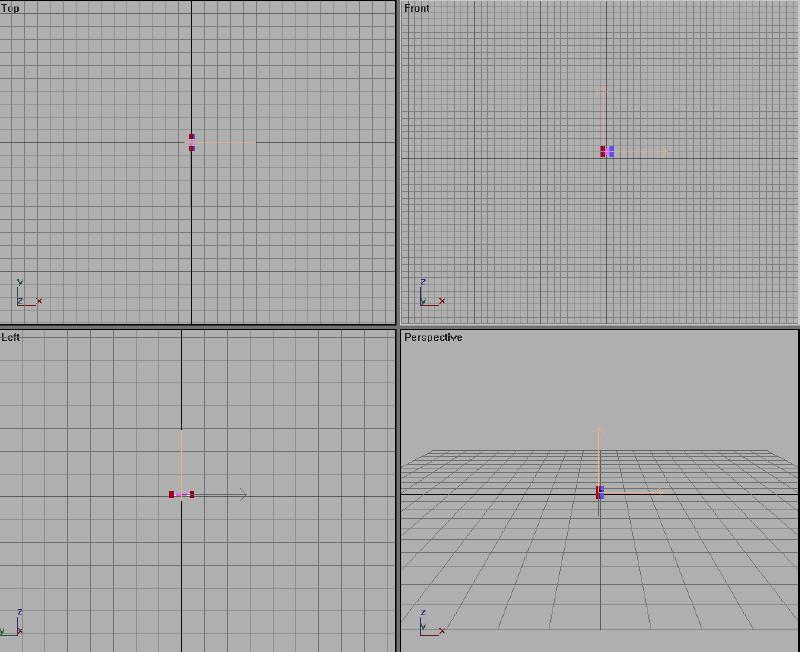
To something like this:
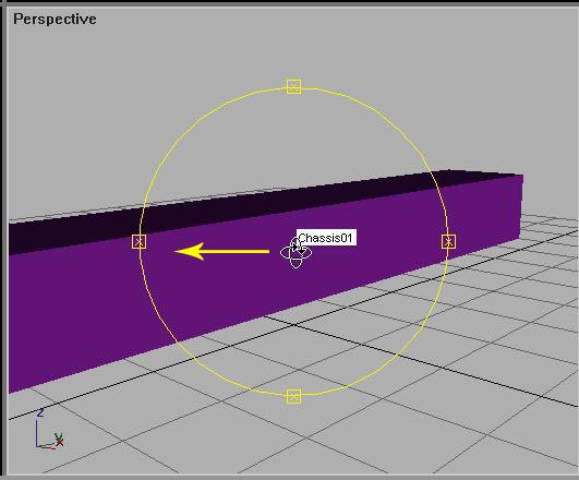
This is much better, but still not exactly right. You should change the Perspective Viewport to give yourself a better view of the object. You do this by rotating the object and using the Zoom tool.
In the lower right corner of the screen, in the same area as
the Zoom Extents symbol, you will find the Arc Rotate symbol.
 Click on
that and you will see a yellow circle appear in the selected viewport. You
want to select the Perspective Viewport.
Click on
that and you will see a yellow circle appear in the selected viewport. You
want to select the Perspective Viewport.
Position the cursor in the center of the circle and press and hold the left mouse button and drag to the left to rotate the object in that direction.
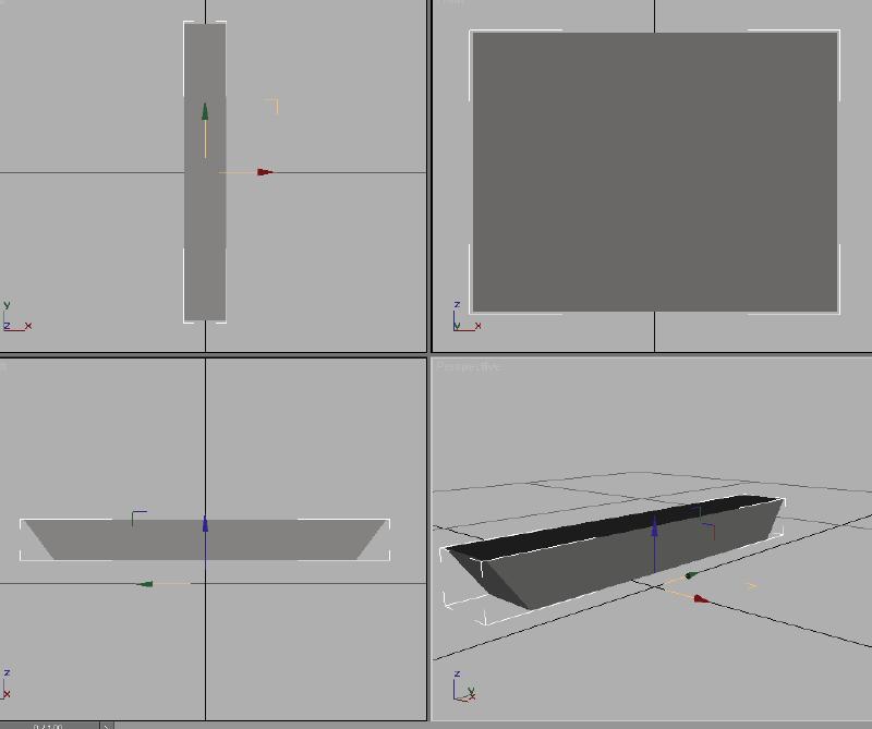
Click on Zoom Extents or use the keyboard shortcut (Ctrl-Shift-Z) to focus the viewport.
That concludes the Freeform method of creating a shape. All other shapes can be created and sized in the same manner. The choice is yours, which method you prefer to use. In some cases you don't have a choice, because dimensional data is not available.
Section 2. How to fix a mesh that appears Gray when a texture is applied
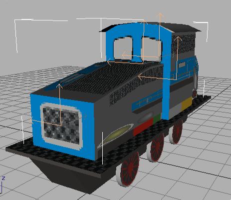
When you create a new part and forget to check the Generate Mapping Coordinates check box, the shape will appear gray in color when you attempt to add a texture to it.
This may appear to be catastrophic and you think you may need to start all over again, recreating the shape. This is not true and can be fixed. Most of the procedures presented here are used and shown in later parts of the tutorial.
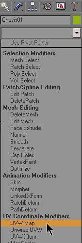
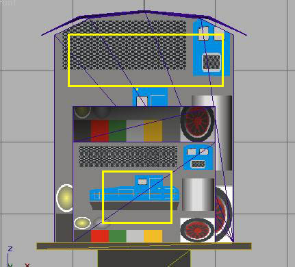
In the toolbox open the list box Modifier List and select UVW Map.
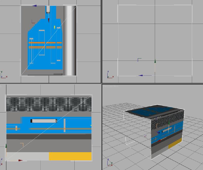
You will see the texture appear in the Front and Top Viewports, but there is no texture on the sides in the Left and Perspective Viewports. This still is not correct.
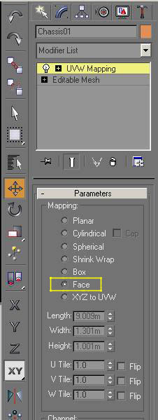
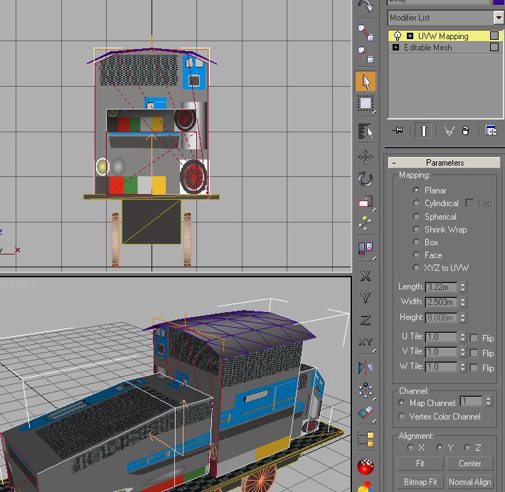
In the Mapping section of the UVW Mapping tool, select Face to map the texture to all the faces of the shape.
Your texture should now appear correctly on the shape and you can return to texturing section you were woking on before correcting this problem. Do not be concerned with leaving the UVW Mapping modifier active. At the end of each texturing step, you will be collapsing the modifier stack and this as well as any other modifiers used will be closed.
Section 3. Connecting Rod connection point values
Section 4. Tessellate method for adding and shaping the roof
New polys for the cabin
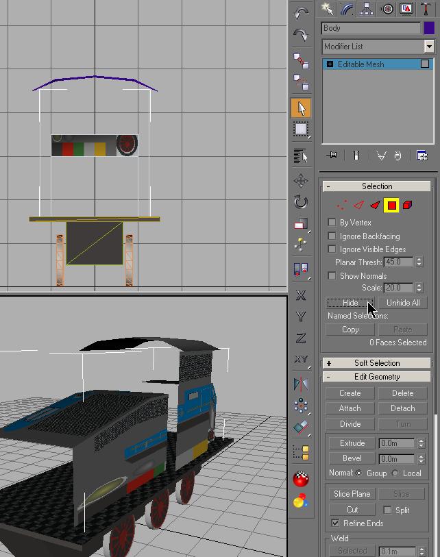
Select the Cabin in the Side Viewport. In the Display toolbox you click Hide
Unselected. All parts except the cabin will be hidden.
Use the Zoom Extents All to enlarge the Viewports.
In the Perspective viewport you can see, that the faces are
only visible from the outside. the side, the Normals are directed to.
Reference : Normals are used to define which side of a face or vertex is
considered the "out" side. The out side of a face or vertex is the side that's
visible in viewports.
Now you have to close the front and back face of the cabin. In
Polygon select mode (don't forget to select the cabin object first) you use the
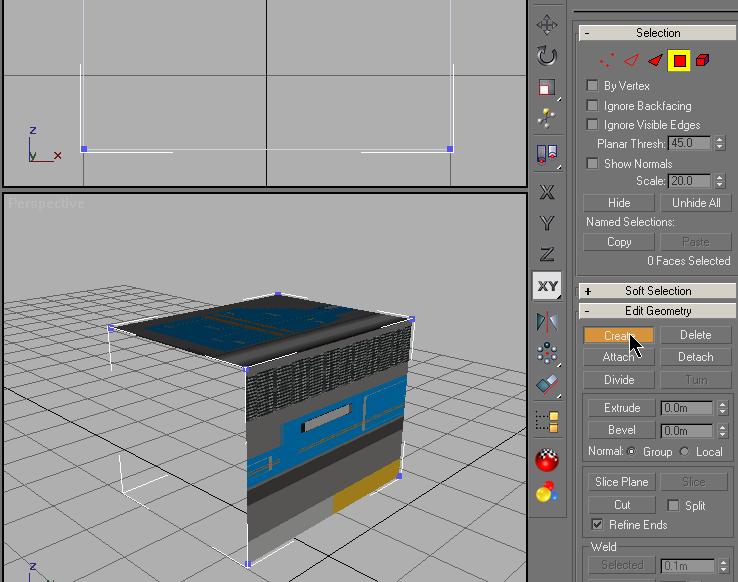
Create command. You do this in the Perspective Viewport.
As shown in the image, you click on the Create button. You see what appear to be
vertices appear at the corners in all the Viewports. I will refer to these as
vertices for the rest of this process.
Caution !
It is essential to create the polygon counterclockwise. Otherwise the Normals would face to the other direction and the polygon would not be visible from the outside.
When you move the mouse pointer into the Perspective Viewport, you see a thin cross hair cursor ...
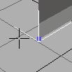 As you move over a vertex, the cursor shape will change to a small cross
This will aid in selecting any vertices that are not visible in the viewport.
Click once on each of the vertices in a counter
clockwise sequence. A thin dotted line follows your cursor's movement. When you
are over the last vertex, double click to complete the creation of the new face.
This is the result:
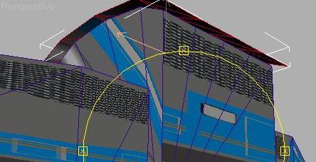
With the view control Arc Rotate you rotate the cabin
into the other direction to make the backside visible.
HINT: Place the cursor in the center of the circle and click and hold the mouse
button while moving the mouse to the left to rotate the object.
Your view should appear almost identical to the first part of this section.
Create the backside of the cabin the same way you did with the front.
The roof
In the Front viewport you change to Vertex Selection mode. Draw a box that
encloses the top and bottom vertices on the right side.. With the Move tool and
the Move Transform-Type-In dialog change the X value to 1.25 meters. Do the same
to the other side, but enter a value of -1.25 meters for the left. Draw a box
enclosing the top set of vertices and enter a value of 4.5 meters in the Z
value. You see the Cabin get wider and taller. Close the Move Transform-Type-In
dialog.
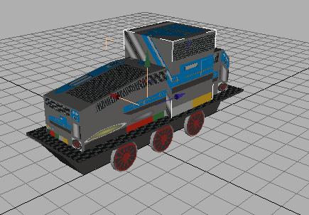
Then in the Display tool you click Unhide All.. Zoom Extents All and the result
should look like this:
Select the Body. You want to join the Body and the Cabin
together. You should still have the Modify tool open.
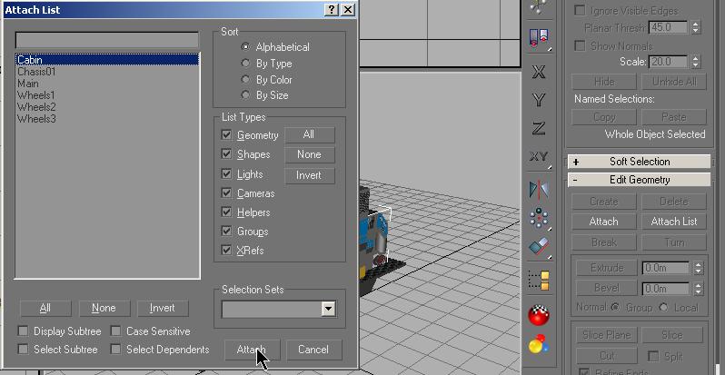
Click on Attach List.
In the dialog box you select Cabin and click the Attach button.
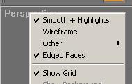
You zoom in the Perspective viewport and change the viewing
options for the viewport to Smooth and Highlights and Edged Faces which can be
found by right-clicking on the word Perspective in the upper left corner of the
Viewport.
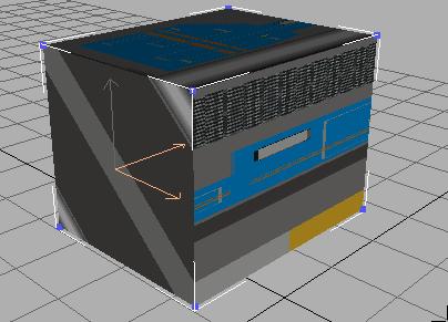
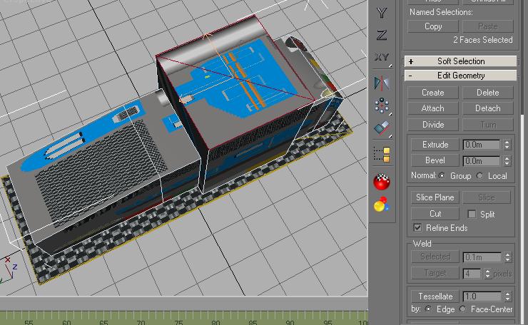
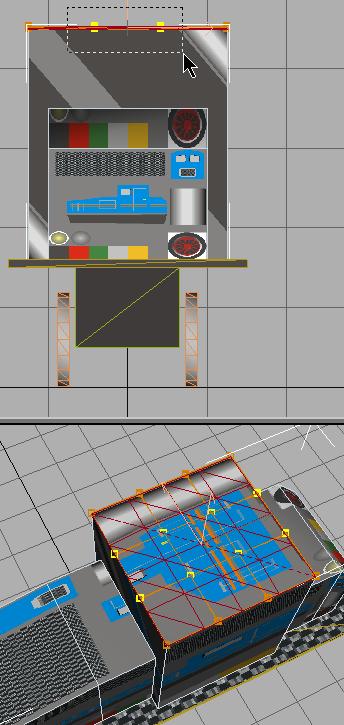
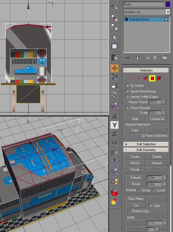
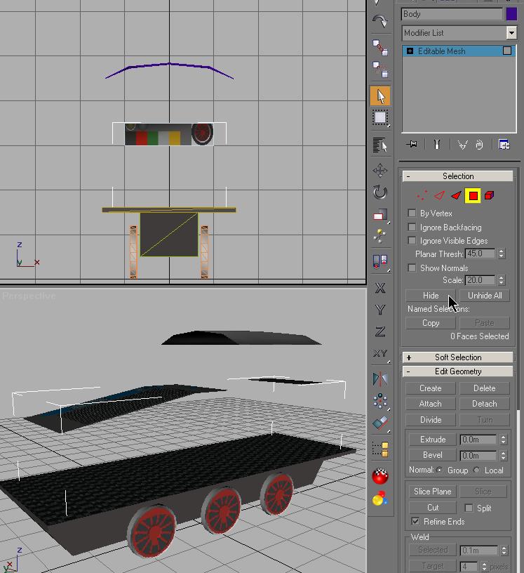
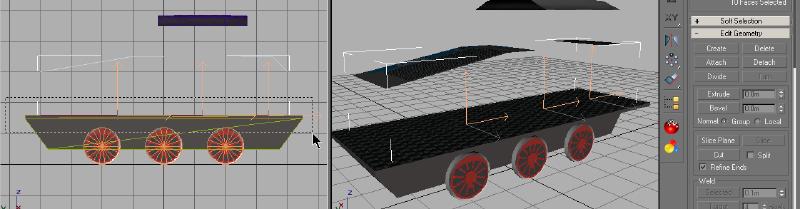
Then you rotate the loco that the roof is seen from above as shown and select the roof's polygons. Make sure not to select the sides of the cabin.
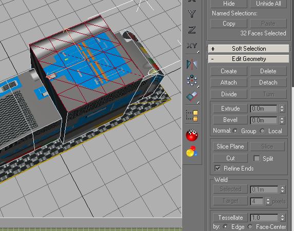
Tessellating the roof
To model the roof as desired, you have to split the polygons into a number of
polygons. The function to do this is the Tessellate function which can be found
in the Edit Geometry section. You type in the value of 1.0 in the field beneath
the Tessellate button and click the button twice. The roof should now look like
in the image below.
You leave all polygons(2) of the roof selected!
REFERENCE:
A tessellation is created when a shape is repeated over and over again covering a plane without any gaps or overlaps. Another word for a tessellation is a tiling
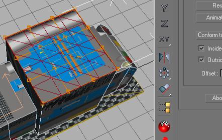
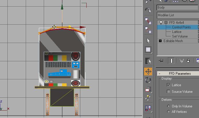
A Free Form Deformation
In the Modify toolbox you select the Free Form Deformations (FFD 4x4x4) from the
modifier list.
An orange control grid appears.
You want to select and manipulate the control points that just
appeared. You can do this in 2 different ways.
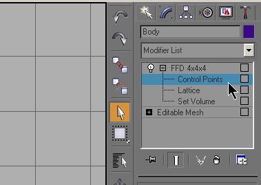
Selecting Control Points (Method 1)
In the Modify toolbox, you opened the modifier FFD 4x4x4.
Click on the + sign to the left and the FFD 4x4x4 expands and displays a tree of sub-objects of the modifier.
Click on Control Points and that is highlighted blue. Nothing changes in any of the Viewports.
Now you can work with the Control Points.
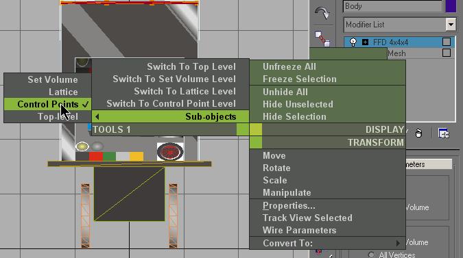
Selecting Control Points (Method 2)
Select any Viewport. Right-click and a context menu appears. Select the option
Sub Objects - Control Points.
You see that in the Modifier stack that FFD 4x4x4 changed from being highlighted
yellow to blue. If you click on the + you will see that Control Points is
selected.
You have accomplished the same thing using a different method.
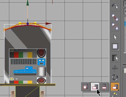
You can select the Control Points in the same manner you used to select vertices. Using the Top Viewport you draw a box enclosing the 2 center Control Points.
The Control Points change color to yellow when selected.
NOTE:
If you wished to de-select any Control Point, hold the Alt key down and draw a box around the point you wish to de-select.
You want to move the control points up with the Select and Move tool. You could do this using the Move Transform-Type-In dialog as you have done in previous sections.
If you have plans that show actual dimensions, that would be
the method to use. In this case, you will see how to perform some free form
modeling.
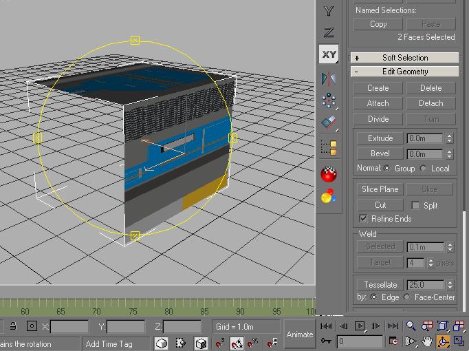
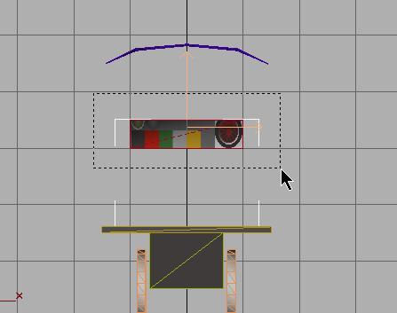
You only want to move selected Control Points up, without any movement to the
left or right.
The easiest way to do this is to click on the green arrow pointing up, in the Front Viewport. (if you don't see this, use the Zoom tool as I have done in the illustration)
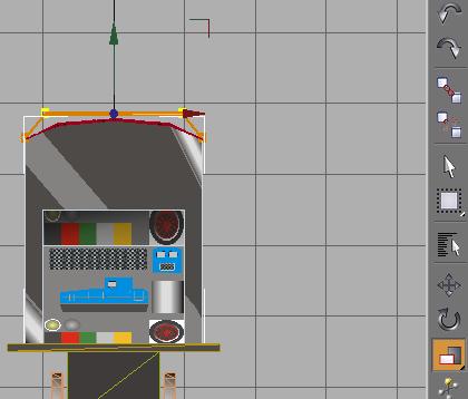
The body of the arrow changes color and movement will be
restricted to up and down.
I place the Move tool on the left selected Control Point and move up. In this
case, I found that trying to use the right selected Control Point was difficult
because it is so close to the X arrow.
When it looks right, stop.
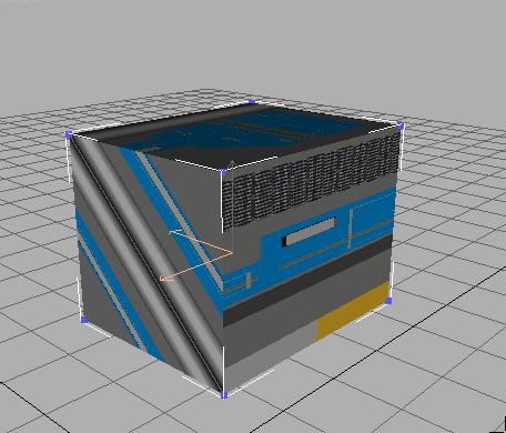
Now you want to move the selected Control Point toward the edges. You will use the Non Uniform Scale tool.
Click on the red X-Axis arrow, so you only move on that axis. Click and hold the Non Uniform Scale tool on the left selected Control Points and move the mouse until you see the Control Points move to the approximate position show in the illustration below and release the mouse button.
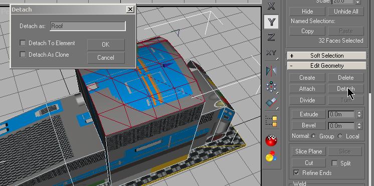
Then you collapse the modifying stack again and switch to Polygon selection mode and leave the roof polygons selected.
You detach the selected polygons and name them Roof.
Stretching the roof
You close the polygon selection mode and select the newly detached roof using
the Select By Name
![]() on the Tools menu.
on the Tools menu.
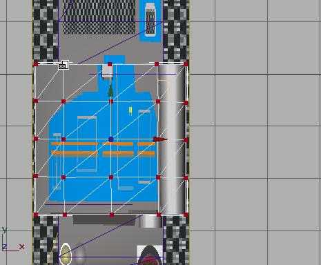
Our goal is to both stretch the length of the roof and to widen the roof over the edges of the cabin. I find that using the Top Viewport for this operation gives me the best view.
Select the Top Viewport. Click on the XY-Axis
![]() on the
Tools menu. This will restrict movements to the X-axis and Y-axis only. Select
all the roof's vertices and stretch them with the Non Uniform Scale tool.
on the
Tools menu. This will restrict movements to the X-axis and Y-axis only. Select
all the roof's vertices and stretch them with the Non Uniform Scale tool.
![]()
This is another "eye-ball" move, with no specific dimensions. I used the edges of the Frame as my guide.
As you move this you will see the changes in all the Viewports.
The faces of the roof are only visible from above due to the direction of their normals. To make the down-facing side visible , you have to copy the roof and flip its normals.
To do so, you deactivate the vertex selection mode and with the Move tool activated, you Shift-Click on the roof to make a copy.
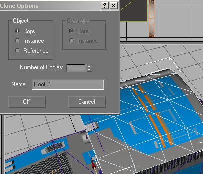
Then you switch to Polygon selection mode (the new object Roof01 is selected automatically) Select all the Roof01 polygons.
Scroll the Miodify rollout down until you see the Surface Properties section.
In the Normals section you click the Flip button.
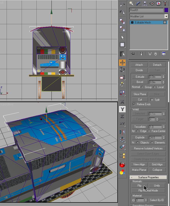
Now you can see the down-facing side of the roof.
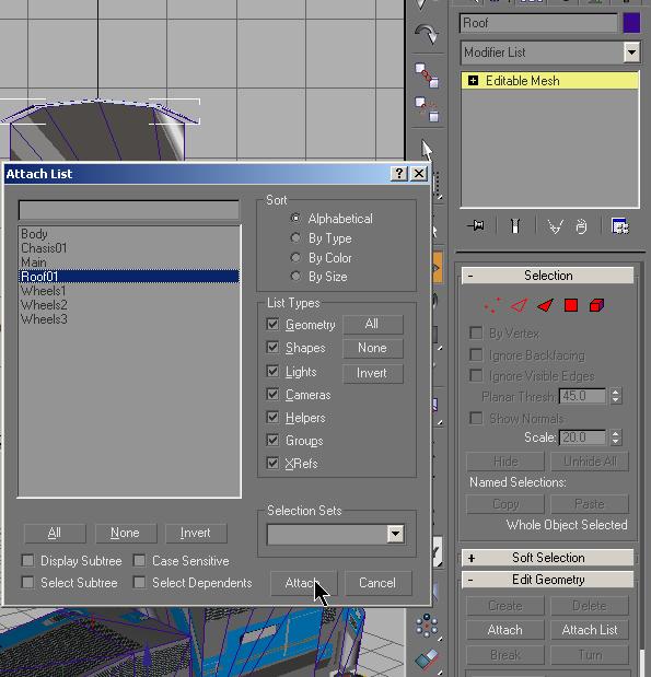
You deactivate the polygon selection mode and select the
primary roof object using Select By Name
![]()
Then you attach the object Roof01 with the roof using Attach List.
With the selected roof you change to the polygon select mode and select all the polygons, if they aren't already selected.
You add the UVW Mapping modifier to the stack.
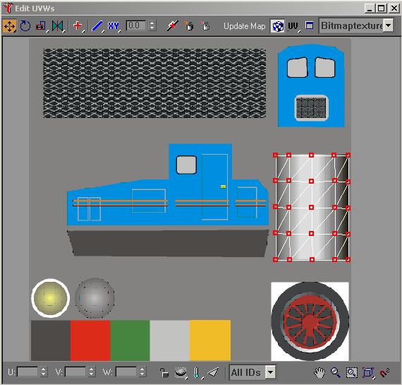
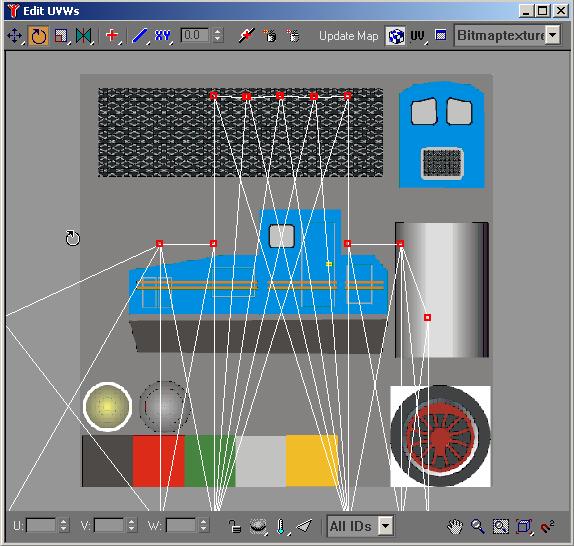
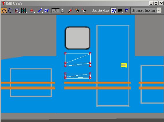
Then you add the Unwrap UVW modifier to the stack and select Edit. With all the vertices selected in the editor, you resize and move the mapping vertices to the roof section of the image.
OK, you can't get the mapping vertices to line up correctly using the tools you know.
You will use a new tool to get the alignment you want.
This is the Horizontal Scaling Tool in the UVW mapping editor.
It will stretch or contract the selected mapping vertices along the horizontal axis only.
The other tool not used here, but shown in the illustration is the Vertical Scaling Tool that does the same thing on the vertical axis.
Using the Scaling Tools and the Move Tool, align the mapping vertices as shown below. Zoom and move the image to get the placement of the mapping vertices as accurate as possible.
You can now close the editor and collapse the stack.
You are finished with the roof. Save your project and you will continue on to the Body.
Mapping the body
First, you map the front and rear of both body and cabin.
Select the Body. In the Modify rollout change to Polygon mode.
You select all the polygons on the front of the cabin first. Press the CTRL-key.
Hold it down and select the polygons on the front as shown in the illustration below.
In the Modifier List select UVW Mapping and add it to the
stack. In the Alignment section, check Y and click on Fit.
This should be the result:
In the Modifier List select Unwrap UVW and add it to the stack.
Open the editor and select all mapping vertices. Resize the mapping grid and position it over the cab/grill area of the image.
Zoom and move the image to give yourself a larger view to work with. See the illustration below:
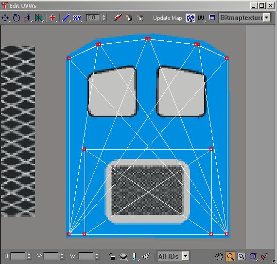
Then you close the editor and collapse the stack. This is the result:
You should still be in the polygon select mode, with the mapped polygons selected. If not, reselect them. Now you Hide the already mapped polygons to prevent them from being re-selected and remapped.
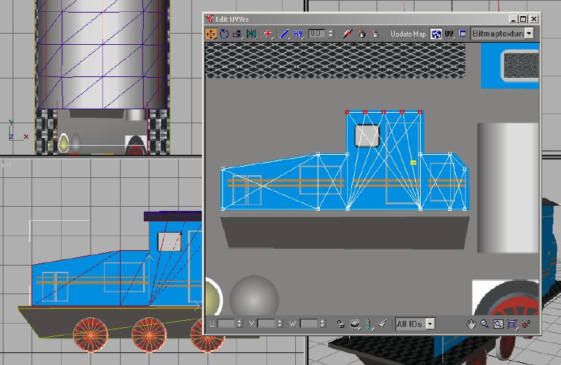
Using the Side Viewport you draw a box to select all the polygons for the sides of the Body.
Now, you select all side-facing polygons.
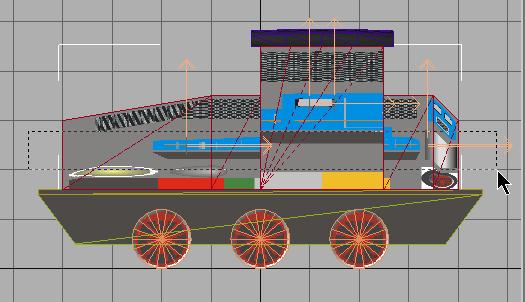
Add the UVW Mapping modifier to the stack. In the Alignment section check X and click on Fit.
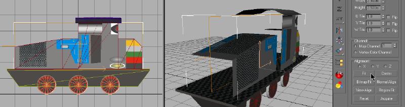
Now you add the Unwrap UVW modifier to the stack and open the editor.
The grid of mapping vertices need to be rotated 90 degrees counter clockwise. Select all mapping vertices and rotate the grid. You should get results similar to the picture below:
Using different combinations of resizing and moves, you want to get the grid aligned to the image as shown below.
You will note that for the final move, I have selected the 5 mapping vertices to move those alone.
WARNING !
Moving small groups of mapping coordinates is not required and should be avoided if you intend to allow others to reskin your model. This was my choice.
I have also done the same with the pair on the front section.
Resizing the mapping grid in any way that does not move all mapping coordinates will skew the image on the mesh. This will cause problems for anyone who wishes to reskin your model.
In this case, where I have moved the 5 upper mapping coordinates to better align the cab windows (in my opinion only) will cause anyone attempting to change the side of the cab problems. Replacing the striping and adding lettering or a logo to the cab will not work. The result will be skewed and not correctly aligned. Resizing of the mapping grid should only be done with all vertices selected.
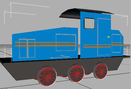
The changes you do in the mapping editor are immediately visible in the Viewports.
You close the editor, collapse the stack and here is the result:
You still have all the side polygons selected. Click on Hide.
Now it's time to get rid of the bottom polygons of the body.
You can't see them, but MSTS has to calculate them. You select the bottom faces as shown and delete them with the Del key.
You see the vertices arrows disappear from the screen.
Now, you select the upper faces of the body.
You add the UVW Mapping and the Unwrap UVW modifiers to the stack.
In the editor, you resize and move the mapping vertices to a solid blue section of the image as shown below.
After leaving the editor and collapsing the stack, you click Unhide All in the polygon selection mode and the body is done.
Don't forget to save the work.
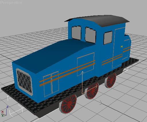
This concludes the Tessellate method for adding the Roof and texturing the body. This method adds some extra polygons to the final model. The remainder of the model construction follows very much the same flow as is shown in the Main Tutorial. You will have the Roof as an added part, when you create the hierarchy preparing the model for export to MSTS.
You now have another GMAX tool that you can use for your own models.