Elvas Tower: Eng Files for USA diesels - Elvas Tower

Jump to content

  • 6 Pages +
  • « First
  • 4
  • 5
  • 6
  • You cannot start a new topic
  • You cannot reply to this topic

Eng Files for USA diesels Looking for data... Rate Topic: -----

#51 User is online   R H Steele 

  • Executive Vice President
  • PipPipPipPipPipPipPipPipPip
  • Group: ET Admin
  • Posts: 3,421
  • Joined: 14-March 13
  • Gender:Male
  • Location:known universe
  • Simulator:Open Rails
  • Country:

Posted 27 August 2021 - 11:34 AM

 darwins, on 26 August 2021 - 10:49 PM, said:

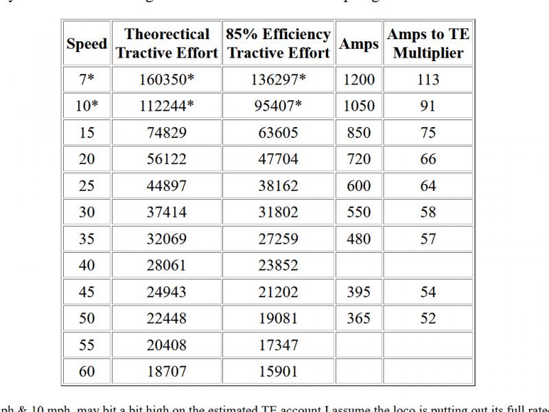
Interesting to see the overall efficiency of transmission in USA being taken as 85%. In UK the figure was taken as 81% generally - 90% efficiency for the generator and then 90% of that again for the traction motors and gearing. From test data collected the actual figure for most locos built in the 1950s was around 76% to 78% over most of the speed range. I think perhaps there is greater efficiency from larger engines. Whatever the engine size the amount of power needed for auxiliaries seems to be somewhere around 30hp - so that particular loss is smaller in proportion to a more powerful engine. Also variation over the speed range. Efficiency in dc transmissions rises as you start each new phase of field weakening and then falls off again until after the final stage the generator is unloaded and the power output drops rapidly.


For North American locos I've found efficiencies in the most modern designs to be higher than 85% --- low to mid 90%s. That's something the manufacturers like to overstate...test docs for efficiency are hard to come by for every loco...but 85% is a good place to start from.

Most Tractive Effort vs Power formulas use a built in eff. of 83 to 85 percent, if I remember correctly. AFAIK ( from readings in the forum posts ) the OR code also uses a constant eff multiplier....which is probably in that range.


The formula I use has efficiency as one the variables...which makes customizing the curves a little easier...especially if you find good test data.

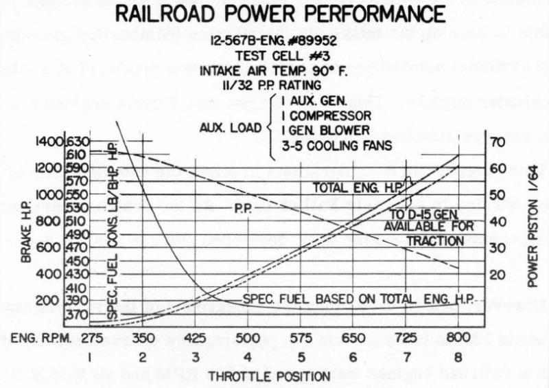
Power needed for the auxiliaries does vary for NA locomotives, when documented in the manuals ( not too often, or you have to dig into the manual and read the whole thing ) - can be from a little above what you stated --- 50hp ( never found any values lower than 50hp ) to 100hp, but I have found documentation of power losses from 125hp to 225hp.

When I cannot find good data I've settled upon using 130hp to 150hp.

I'm thinking that Max TE should be available for each notch in the curves but limited by the design of the traction motors. I hope a member with more knowledge or experience with the subject will post.
I do not believe the OR code currently supports traction motors vs. amperage ( or gearing vs. speed ) in diesel-electric locomotives.

MSTS has MaxCurrent parameters in the eng file but from what I read it is not related to the traction motors, but rather to the amount of current for use --- the Richter manual uses the term "transformer" and states "mainly used to display the proper motor current on cab ammeter".

I don't know if OR uses this MSTS parameter.

Al Krug's document is interesting in that shows how to construct interrelated tables that could be used to limit tractive effort based upon amperage for a specific locomotive. I'm still in the process of trying to understand what variables need to be known, and how to construct a set of tables for a specific locomotive.

It has been interesting & entertaining teaching myself about the physics of locomotives, the journey continues. The more I learn the more I know...how little I know.


#52 User is offline   ErickC 

  • Superintendant
  • Group: Status: Elite Member
  • Posts: 1,001
  • Joined: 18-July 17
  • Gender:Male
  • Location:Hastings, MN, US
  • Simulator:ORTS
  • Country:

Posted 27 August 2021 - 03:48 PM

The power for auxiliaries is irrelevant in North American diesels because they are rated at traction horsepower, not gross horsepower. A 16-567C produces more than 1,750 HP at the flywheel, but it's rated for the guaranteed power into the generator, which is 1,750 HP. Note also that generators and alternators have very real limits. One of the reasons EMD switched to alternators on DC traction was that the number of transition stages required to keep higher-power locomotives from frying their equipment was getting out of hand with the 35 series. Here is data for a 12-567B:

Attached Image: EMD 12-567B.JPG

#53 User is offline   engmod 

  • Open Rails Developer
  • PipPipPipPipPipPipPip
  • Group: ET Admin
  • Posts: 1,759
  • Joined: 26-February 08
  • Gender:Male
  • Location:Eltham, Victoria, Australia
  • Simulator:ORNYMG
  • Country:

Posted 27 August 2021 - 04:25 PM

 ErickC, on 26 August 2021 - 06:04 PM, said:

I should note that I am uncertain to what degree these systems were optional, especially on export units. I only have reference materials for North American domestic locomotives.


Our g6b ( switcher ) did not have any wheelslip controls and was NOT allowed to have sand on board.
Our g8b ( roadswitcher ) did have the red light and drop a notch wheelslip control and did have sand on board.

#54 User is offline   engmod 

  • Open Rails Developer
  • PipPipPipPipPipPipPip
  • Group: ET Admin
  • Posts: 1,759
  • Joined: 26-February 08
  • Gender:Male
  • Location:Eltham, Victoria, Australia
  • Simulator:ORNYMG
  • Country:

Posted 27 August 2021 - 04:28 PM

 R H Steele, on 27 August 2021 - 11:34 AM, said:

I'm thinking that Max TE should be available for each notch in the curves but limited by the design of the traction motors


Max TE can only be had at max current.
max current is not available in the lower notches.

#55 User is online   R H Steele 

  • Executive Vice President
  • PipPipPipPipPipPipPipPipPip
  • Group: ET Admin
  • Posts: 3,421
  • Joined: 14-March 13
  • Gender:Male
  • Location:known universe
  • Simulator:Open Rails
  • Country:

Posted 27 August 2021 - 05:08 PM

 ErickC, on 27 August 2021 - 03:48 PM, said:

The power for auxiliaries is irrelevant in North American diesels because they are rated at traction horsepower, not gross horsepower. A 16-567C produces more than 1,750 HP at the flywheel, but it's rated for the guaranteed power into the generator, which is 1,750 HP. Note also that generators and alternators have very real limits. One of the reasons EMD switched to alternators on DC traction was that the number of transition stages required to keep higher-power locomotives from frying their equipment was getting out of hand with the 35 series. Here is data for a 12-567B:

I agree, but not irrelevant for my purposes --- I wanted to know what Gross hp was to provide more complete information in my comment lines in the Std Eng files and also the formula from the Virginia Tech paper starts with shaft horsepower and uses efficiency as a variable --- so agreed, not normally useful for most practical purposes. Also I found it interesting just as knowledge and understanding about locomotive power plant design. I was careful to make sure that the traction hp was the correct value for the formula, and also in the comment line in the Std Eng file, if you have found any errors or questionable values in that regard, please let me know by PM, with reference to tech docs, if applicable. Thanks.

Also, there is historical use of the BHP -- it was ( if I remember correctly ) between Fairbanks Morse and Alco, one of those two used BHP and the other used traction hp, it was a sales battle -- with some hp-bs thrown in for good measure. http://www.elvastower.com/forums/public/style_emoticons/default/smile.gif
Of course generators and alternators ( and traction motors also ) have limitations imposed by design and physics....I'm just wondering if those limitations can be coded into OR to provide realistic operating limits on traction. Thanks for the data Erick, you always seem to have something relevant close at hand.

#56 User is online   R H Steele 

  • Executive Vice President
  • PipPipPipPipPipPipPipPipPip
  • Group: ET Admin
  • Posts: 3,421
  • Joined: 14-March 13
  • Gender:Male
  • Location:known universe
  • Simulator:Open Rails
  • Country:

Posted 27 August 2021 - 05:15 PM

 engmod, on 27 August 2021 - 04:28 PM, said:

Max TE can only be had at max current.
max current is not available in the lower notches.

Agreed, just as the Krug paper shows. Question is...can the lower notch current amounts be used to regulate, limit, or more accurately reflect the TE at those notches? Would that give users to the ability to have more realistic TE curves. ( or is it necessary? )

Attached thumbnail(s)

  • Attached Image: bandicam 2021-08-27 18-11-53-888.jpg


#57 User is offline   ErickC 

  • Superintendant
  • Group: Status: Elite Member
  • Posts: 1,001
  • Joined: 18-July 17
  • Gender:Male
  • Location:Hastings, MN, US
  • Simulator:ORTS
  • Country:

Posted 27 August 2021 - 06:06 PM

 R H Steele, on 27 August 2021 - 05:08 PM, said:

I agree, but not irrelevant for my purposes --- I wanted to know what Gross hp was to provide more complete information in my comment lines in the Std Eng files and also the formula from the Virginia Tech paper starts with shaft horsepower and uses efficiency as a variable --- so agreed, not normally useful for most practical purposes.

I was referring less to your post and more to the part of the one above that talked about efficiency with respect to power into the generator. For the purposes of calculating overall efficiency, losses before the generator aren't important because the power into the generator is what our diesels are rated at, meaning the losses are downstream. This isn't universal across the world, of course. For our purposes it is useful to know gross HP minus accessory load because the actual power to the generator may be greater than nominal - the 16-567B is going to have much more gross power to play with despite a similar accessory load to a 12-567B. I suspect this may account for part of the reason why efficiency is often slightly better than nominal.

#58 User is online   pschlik 

  • Conductor
  • Group: Status: Active Member
  • Posts: 325
  • Joined: 04-March 15
  • Gender:Male
  • Simulator:OpenRails - Unstable
  • Country:

Posted 27 August 2021 - 06:41 PM

Getting the right starting tractive effort is really important to proper operations, it's way more interesting to drive something when (like in real life) using more than notch 4 starts to risk slipping. And NO, the maximum tractive effort is NOT available in all throttle positions, as various images show.

SD40-2? Nope, you won't get 131,000 pounds of tractive effort unless you are in notch 7 or 8. NASA's JPL figured this out (don't ask me why NASA or JPL was doing anything with trains I really don't know) and I trust NASA.
https://i.imgur.com/8oZpTZR.png
How about the smaller brother, the GP40-2? Nope, still not getting max tractive effort unless you use max throttle. (yes I know this exact graph was posted earlier, shush)
https://i.imgur.com/NlhZ0Rz.png


Want something a bit more modern in the AC4400CW...and uh, nope, still not getting maximum tractive effort unless you use maximum throttle. And Union Pacific figured this stuff out so they could do simulations of their trains. This is the exact kind of dataset that is built to be tossed into Open Rails.
https://i.imgur.com/8cioAZ9.jpg

This is because basically every self-respecting road switcher will have circuitry set up such that each throttle position will allow for only so much current at the generator (and subsequently, only so much current [ie: tractive effort] at the motors). This allows for nice, controlled starts with small amounts of tractive effort.
https://i.imgur.com/K8DgUqt.png


Now you can come up with situations where the current limit is much more aggressive than that, where even low power settings produce high current. That would be a full field start (and the Brits really liked to use full field starts in their early diesels). But even with a full field start like a Deltic does, the maximum possible tractive effort in minimum power is still going to be way less than the maximum tractive effort at full power.
https://i.imgur.com/1dlOged.png

The limitations of electricity generation simply do not allow for generating maximum motor current at low RPMs. Implying that notch 1 and notch 8 could possibly achieve the same starting tractive effort is a real breach of reality.


Instead, if we look back at that AC4400CW (mostly because it's the easiest graph to read), the starting tractive effort in each notch is obviously different, but the spacing between notches is (interestingly) not constant by any means. The starting tractive effort shoots up rapidly between notches 1 thru 4, from 15000 pounds to 52000 to 84000 then all the way to 111000 pounds. Notch 4 and we are already at 62% of maximum tractive effort. Comparing starting tractive effort to throttle setting makes a sort of concave downward parabola. Oh, and older locomotives do the same thing according to NASA, with surprisingly similar results. It's almost like there's some standard configuration locomotive manufacturers have just stuck to for ages.
https://i.imgur.com/n4xcUJR.png

And I have this all implemented in my physics set. For simplicity, I have been going with the same formula as the AC4400CW on all of my locomotives. Just note that when I'm talking about the "% of starting tractive effort" I mean the % of the absolute maximum 'the traction motors are about to explode' effort, not the adhesion limited tractive effort. If you use this correlation on the adhesion limited tractive effort the results will be bogus.

All in all, I've found driving with this very satisfying. Notch 2 or notch 3 is usually enough to start most trains, and as you speed up you need to notch out slowly to keep control of the train. Try to slam it to run 8 like you might be used to and that's a recipe for wheel slip (just like in real life).


#59 User is offline   Weter 

  • Member, Board of Directors
  • PipPipPipPipPipPipPipPipPipPip
  • Group: ET Admin
  • Posts: 6,884
  • Joined: 01-June 20
  • Gender:Not Telling
  • Simulator:ORTS
  • Country:

Posted 04 September 2021 - 05:04 AM

@Gerry and others:
Non-linear efficiency of transmission can be tied with magnetizing effects as saturation.
Which is natural conditions of electro-magnetic machines iron.

  • 6 Pages +
  • « First
  • 4
  • 5
  • 6
  • You cannot start a new topic
  • You cannot reply to this topic

1 User(s) are reading this topic
0 members, 1 guests, 0 anonymous users