 Log In
 Register Now!
 Help
Help

Eng Files for USA diesels
Looking for data...
Rate Topic:

#41

- Hostler
-

- Group: Status: Active Member
- Posts: 76
- Joined: 23-February 12
- Gender:Male
- Simulator:Open Rails
-
Country:

Posted 23 August 2021 - 06:38 PM
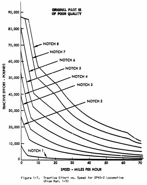
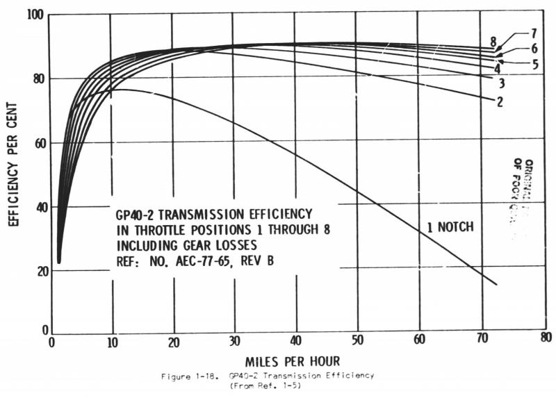
I feel like I posted this diagram before on this site, but I feel that the EMD GP40-2 Tractive Effort vs. Speed chart is quite useful for reference here. As you can see, power is very much not linear but rather exponential, while tractive effort follows a different, somewhat linear progression versus throttle. And for another matter, transmission efficiency is not a constant, but varies somewhat over the speed range. You can see that EMD's setup for notch 1 results in rather low efficiency at high speeds, but in practice this matters little.
#42
- Foreman Of Engines
-

- Group: Status: Contributing Member
- Posts: 944
- Joined: 01-March 15
- Gender:Male
- Simulator:Alföld
-
Country:

Posted 23 August 2021 - 11:45 PM
Hello.
Yes, the ORTSMaxTractiveForceCurves or ORTSTractionCharacteristics table must be set based on these curves. I like the latter. Of course, this requires an ORTSDieselEngines block with good settings. ThrottleRPMTab and DieselPowerTab are the most important. Whichever diesel I did this way was good.
Regards Laci 1959
#43
- Fireman
-
- Group: Status: Active Member
- Posts: 171
- Joined: 24-January 18
- Gender:Male
- Simulator:Open Rails
-
Country:

Posted 24 August 2021 - 12:20 AM
It is more reliable to use the ORTSMaxTractiveForceCurves parameter for diesel traction. He sometimes has a problem with the ORTSTractionCharacteristics parameter (after some updates OR).
Conversely, electric traction with the ORTSTractionCharacteristics parameter works well.
Conversely, electric traction with the ORTSTractionCharacteristics parameter works well.
#44
- Open Rails Developer
-

- Group: Status: Elite Member
- Posts: 1,889
- Joined: 24-June 11
- Gender:Male
-
Country:

Posted 24 August 2021 - 12:28 AM
Lamplighter, on 24 August 2021 - 12:20 AM, said:
It is more reliable to use the ORTSMaxTractiveForceCurves parameter for diesel traction. He sometimes has a problem with the ORTSTractionCharacteristics parameter (after some updates OR).
Conversely, electric traction with the ORTSTractionCharacteristics parameter works well.
Conversely, electric traction with the ORTSTractionCharacteristics parameter works well.
As far as the OR code is concerned these are treated exactly the same, so in theory one parameter could be dropped.
#45
- Executive Vice President
-

- Group: ET Admin
- Posts: 3,439
- Joined: 14-March 13
- Gender:Male
- Location:known universe
- Simulator:Open Rails
-
Country:
Posted 24 August 2021 - 10:25 AM
steamer_ctn, on 24 August 2021 - 12:28 AM, said:
As far as the OR code is concerned these are treated exactly the same, so in theory one parameter could be dropped.
There's an early thread here at ET that was about these two parameters -- Matej Pacha, recommeded keeping both active.
MaxTractive vs MaxTraction
Also...this thread started by plainsman...Traction
...and many users have already implemented one or the other of these two parameters.
#46
- Executive Vice President
-
- Group: ET Admin
- Posts: 3,439
- Joined: 14-March 13
- Gender:Male
- Location:known universe
- Simulator:Open Rails
-
Country:
Posted 26 August 2021 - 01:29 PM
sim-al2, on 23 August 2021 - 06:38 PM, said:
.... And for another matter, transmission efficiency is not a constant, but varies somewhat over the speed range. You can see that EMD's setup for notch 1 results in rather low efficiency at high speeds, but in practice this matters little.
Interesting, can you please provide a link to that source, or the name and authors of the original doc/study/tech paper that are the source of the graphs? I would like to read the whole document. Thanks.
It's interesting because all the formulas I've found use a constant for the transmission efficiency.
I just happen to be reading Al Krugs "Amperage to Tractive Effort Table for an SD40-2" and even Mr. Krug considers transmission eff. a constant for a specific locomotive design.
Quote
But the generator (alternator), wiring, traction motors, and gearing are not 100% efficient. There is some power loss in each of them. I feel an efficiency of about 85% is a good number to use based on decades of field experience making calculations of Hp, tonnage, grade, and speeds while running actual trains. Thus I have included an 85% efficiency column in the chart which gives a close approximation of the actual tractive effort obtained. The Multiplier column is the multiplier needed to be applied to the amps to get the 85% traction effort figure. You can see this is not a single number. Since this chart is for but a single class of a single model and the multipliers are not a constant you can see that a single conversion constant for amperage to tractive effort for all models is not possible.
Most papers usually consider Transmission Eff to be as described above, although I've read a couple that -- when defining their terms --- mean overall efficiency from power-at-the-shaft to power-at-the-rail, or some other definition specific to their study.
#47
- Superintendant
-
- Group: Status: Elite Member
- Posts: 1,001
- Joined: 18-July 17
- Gender:Male
- Location:Hastings, MN, US
- Simulator:ORTS
-
Country:
Posted 26 August 2021 - 05:36 PM
engmod, on 19 August 2021 - 03:49 PM, said:
This is true for the first generation diesels as they had no control of current.
This is absolutely not correct, first-generation EMD roadswitcher locomotives had these systems. You can see (and hear) it operating here: https://www.youtube....h?v=K1auERUXODs
And here: https://youtu.be/U9eV-19IMng?t=180
And here: https://youtu.be/U9eV-19IMng?t=180
The engine RPM oscillating is caused by the sudden changes in load by the wheel slip control system (which also drops sand) happening faster than the governor can react. From the GP7 operator manual:
Quote
317 Wheel Slip Control If wheel slipping occurs the wheel slip control, located in the electrical control cabinet behind the power contactors, will operate. This will light the wheel slip indicator on the engineer's instrument panel in the cab. Wheel slip action automatically reduces the power output of the main generator which reduces the traction motor torque, stopping the slipping.
Second-generation locomotives introduced an improved version of this system (IDAC), and the Dash-2 line introduced a transistorized system (WS10) that was functionally identical. EMD introduced wheel creep with the radar-controlled Super Series (which did not perform well) on the 50-series in the late 1970s, which was replaced by improved systems (mod3, EM2000) on later units (SD60, SD70, et c.). Sometime in the 1980s, GE introduced wheel creep on an improved version of its Sentry system. Previous iterations of Sentry and earlier systems were roughly equivalent to the pre-Super Series EMD systems. For example, the U25B manual says:
Quote
WHEEL SLIP
If any wheels slip during locomotive operation, the following occurs:
1. A light brake application and a slight reduction in excitation occurs automatically on the locomotive unit that is slipping.
2. When wheels stop slipping, brake application is removed automatically.
3. If wheels continue to slip for more than 2 or 3 seconds, wheel slip lamp (on master controller stand) lights and sand is automatically applied to the wheels of affected unit only. If slip persists, excitation is gradually reduced automatically.
The ability of the locomotive to regulate its power output to reduce slip is, however, completely separate from its ability to exceed amperage limits at low speeds (i.e. below the speed of max continuous tractive effort). Such protection was indeed not present on first-generation diesels. The Dash-2 line has a circuit breaker for overload protection.
#48
- Open Rails Developer
-
- Group: ET Admin
- Posts: 1,774
- Joined: 26-February 08
- Gender:Male
- Location:Eltham, Victoria, Australia
- Simulator:ORNYMG
-
Country:
Posted 26 August 2021 - 05:58 PM
This is absolutely not correct, first-generation EMD roadswitcher locomotives had these systems.
Thanks Erick.
My experience came from a first generation EMD switcher ( g6b ) rather than a roadswitcher, our roadswitcher ( g8b ) had the systems but I incorrectly assumed it was a gen 2 unit.
Thanks Erick.
My experience came from a first generation EMD switcher ( g6b ) rather than a roadswitcher, our roadswitcher ( g8b ) had the systems but I incorrectly assumed it was a gen 2 unit.
#49
- Superintendant
-
- Group: Status: Elite Member
- Posts: 1,001
- Joined: 18-July 17
- Gender:Male
- Location:Hastings, MN, US
- Simulator:ORTS
-
Country:
Posted 26 August 2021 - 06:04 PM
engmod, on 26 August 2021 - 05:58 PM, said:
This is absolutely not correct, first-generation EMD roadswitcher locomotives had these systems.
Thanks Erick.
My experience came from a first generation EMD switcher ( g6b ) rather than a roadswitcher, our roadswitcher ( g8b ) had the systems but I incorrectly assumed it was a gen 2 unit.
Thanks Erick.
My experience came from a first generation EMD switcher ( g6b ) rather than a roadswitcher, our roadswitcher ( g8b ) had the systems but I incorrectly assumed it was a gen 2 unit.
I should note that I am uncertain to what degree these systems were optional, especially on export units. I only have reference materials for North American domestic locomotives.
#50
- Superintendant
-
- Group: Status: Elite Member
- Posts: 1,237
- Joined: 25-September 17
- Gender:Male
- Simulator:Open Rails
-
Country:

Posted 26 August 2021 - 10:49 PM
Interesting to see the overall efficiency of transmission in USA being taken as 85%. In UK the figure was taken as 81% generally - 90% efficiency for the generator and then 90% of that again for the traction motors and gearing. From test data collected the actual figure for most locos built in the 1950s was around 76% to 78% over most of the speed range. I think perhaps there is greater efficiency from larger engines. Whatever the engine size the amount of power needed for auxiliaries seems to be somewhere around 30hp - so that particular loss is smaller in proportion to a more powerful engine. Also variation over the speed range. Efficiency in dc transmissions rises as you start each new phase of field weakening and then falls off again until after the final stage the generator is unloaded and the power output drops rapidly.