Elvas Tower: Wishes for improvement of braking systems - Elvas Tower

Jump to content

  • 68 Pages +
  • « First
  • 55
  • 56
  • 57
  • 58
  • 59
  • Last »
  • You cannot start a new topic
  • You cannot reply to this topic

Wishes for improvement of braking systems Adding and correcting of features Rate Topic: -----

#561 User is offline   pschlik 

  • Conductor
  • Group: Status: Active Member
  • Posts: 368
  • Joined: 04-March 15
  • Gender:Male
  • Simulator:OpenRails - Unstable
  • Country:

Posted 14 July 2023 - 09:09 PM

My improvements have started to appear in unstable versions. As mentioned in my previous post, you can look at the pull request for documentation on the features, or in one of my most recent commits to see what I added to the manual.

For those who do not want to mess with a dozen new tokens, I have a mod for the TS starter route which includes all my physics work from the last 2 years (and that includes updates to make things use the new brake system features). Take the stuff in this ZIP and unzip it inside the TRAINSET folder of a clean install of the TS starter route. I believe there have been a couple of different versions of the TS starter route, and this mod will only work with one of the two. In any case, it should be this download link. No additional file manipulation is needed beyond copying and pasting into the correct folders, though if you want freight car sounds you will need the NAVS Car Sounds v2.5 pack (NAVSFR10.zip on TrainSim.com, can't link directly to the download from here) installed.

Attached File  PSC Physics Enhancement TS Starter Route.zip (1.21MB)
Number of downloads: 83


Some things to look for to verify changes are working (first of all, you need to be on the most recent unstable build for any of this to have a chance at functioning!)
  • Making a minimum reduction causes a very fast reaction along the entire length of the train (that's quick service)
  • Reductions in the brake pipe propagate unnaturally quickly (that's accelerated application)
  • Releasing the train brakes causes a rapid and substantial increase in brake pipe pressure all along the train, at the expense of emergency reservoir pressure reduction (that's quick release)
  • During release from heavy applications, aux res pressure at the front of the train will lag behind the brake pipe pressure, while it'll keep up just fine at the rear (that's uniform charging)
  • If you do an emergency application (this mod uses Cesar's emergency vent valves, so you'll be unable to add air to the brake pipe for 2 minutes after an emergency application) and subsequently release, air from the aux res and brake cylinder will be sent to the brake pipe to speed up the release a lot (that's accelerated emergency release)
  • It may be hard to spot, but the rolling stock won't actually produce any brake force until there's already a few psi in the brake cylinder, which is simulating the resistance of the cylinder return spring

Note that it doesn't matter if you drive the grain train or the double stack. Both types of train cars have the same implementation of an ABDW control valve, which includes all of the aforementioned features. I would have liked to include something with just the ABD valve so you could see how slow applications are without accelerated application, but the free route doesn't have anything fitting that description.

Oh, and I should also mention that, like in real life, these features can cause trouble. If you don't wait for the brake pipe to recharge and make only a minimum reduction it is entirely possible that the combination of quick service and quick release will cause the entire train to release instead of sticking at a minimum reduction.

#562 User is offline   darwins 

  • Superintendant
  • Group: Status: Elite Member
  • Posts: 1,252
  • Joined: 25-September 17
  • Gender:Male
  • Simulator:Open Rails
  • Country:

Posted 14 July 2023 - 10:15 PM

Thank you. This is excellent news. I will try to work out how these apply to UIC standard systems. (That may take some time!) Also it would be good if someone could work out what values are appropriate for historical US triple valves - P, L, H, K, PC, UC, AF...

The way in which this has been done is fortunately independent of propagation rate of the brake pipe.

This is something that now needs to be looked at. The existing model gives values for longer trains that would require some degree of acceleration. The default can also give times that are too long for short trains and too rapid for long trains. They don't seem to fit the way in which air moves along the pipe.

I was hoping Cesar would have a look at the physics of this. Two factors that would need to be included to get a robust model would be:

( a ) Systems without Equalising Reservoirs. When a fixed volume of air is let into or out of the brake pipe then the resulting air pressure will spread out along the train until it is even all along. Early air brake systems did not include equalising reservoirs. Some railways continued to use simple "three way cocks" without equalising reservoirs into the middle of the twentieth century. (We have some preserved locos running on a heritage line in UK with this arrangement today!)

( b ) Different brake pipe diameters. In USA brake pipes were increased from 1 inch (25mm) to 1.25 inch (32mm) at a very early date. Many railways around the world continued to use 1 inch pipes until at least the 1970s and probably some still do so today, as UIC specifications include both 25mm and 32mm pipes.

#563 User is offline   darwins 

  • Superintendant
  • Group: Status: Elite Member
  • Posts: 1,252
  • Joined: 25-September 17
  • Gender:Male
  • Simulator:Open Rails
  • Country:

Posted 15 July 2023 - 05:45 AM

I was rather hoping that the new parameters (together with those we already have) would provide a solution to modelling the various UIC distributors. I am working my way through the excellent Hungarian website. This is the first problem that I am not sure how to solve

Quote

It is now an international (UIC) regulation that the three-pressure triple valve must also cause complete release if the pressure in the main line rises above 4.85 bar. In practice, this means, on the one hand, that the release time of the valve is faster: even the triple valves at the end of long trains empty the brake cylinder relatively quickly if the main line pressure rises above 4.85 bar. On the other hand, it means that above 4.85 bar main line pressure, we can only talk about two-pressure triple valves (that is, a brake that does not have graduated release)"


So in other words if we have BrakeEquipmentType( Graduated_Release_Triple_Valve ) or ( Distributor ) the graduated release only applies whilst the ABP pressure is below 4.85 bar - above that point, even for a small pressure increase, the triple valves must change from "Lap" or "Apply" to "Release" and remain in the "Release" state until ABP pressure again falls to 4.85 bar or less.

Is there a way to do this? Or would another parameter be required?


#564 User is offline   darwins 

  • Superintendant
  • Group: Status: Elite Member
  • Posts: 1,252
  • Joined: 25-September 17
  • Gender:Male
  • Simulator:Open Rails
  • Country:

Posted 15 July 2023 - 07:06 AM

Looking at what is and what is not possible, another problem for the laundry list might be two-stage braking. This has been mentioned before and is normally achieved by using a higher brake cylinder pressure at higher speeds:

Quote

Since the value of the sliding friction coefficient between the cast iron brake blocks and the wheel decreases with increasing speed, the braking distance would increase to an intolerable extent. In the higher speed range, this can be offset by increased brake block force (or by using disc brakes or rail brakes). This practically means a higher (4 bar) brake cylinder pressure. In practice, such a car equipped with a high-performance brake ("rapid or R brake"), which represents a type of fast-acting brake, brakes with higher brake cylinder pressure in a higher speed range, and in a lower speed range, it "releases" the high brake cylinder pressure and continues to brake with "passenger train" (P)braking until it stops.


It may be that there are two different speeds for activating and de-activiting the higher brake cylinder pressure. For example increased brake cylinder pressure is activated when speed rises above 80 km/h but once activated the increased brake cylinder is then released when speed drops below 50 km/h.

AFAIK, in the UIC context, two stage braking is only required for vehicles with cast iron brake shoes. Vehicles with disc brakes will use the higher pressure (or greater brake force) at all speeds when in the ® or <R> mode.

#565 User is offline   pschlik 

  • Conductor
  • Group: Status: Active Member
  • Posts: 368
  • Joined: 04-March 15
  • Gender:Male
  • Simulator:OpenRails - Unstable
  • Country:

Posted 15 July 2023 - 10:54 AM

View Postdarwins, on 14 July 2023 - 10:15 PM, said:

Thank you. This is excellent news. I will try to work out how these apply to UIC standard systems. (That may take some time!) Also it would be good if someone could work out what values are appropriate for historical US triple valves - P, L, H, K, PC, UC, AF...


Most of what I have added isn't relevant for the older triple valve types. Uniform charging and quick service appeared with the AB valve, the ABD valve added quick release, and ABDW and later have accelerated application.

View Postdarwins, on 14 July 2023 - 10:15 PM, said:

The way in which this has been done is fortunately independent of propagation rate of the brake pipe.

This is something that now needs to be looked at. The existing model gives values for longer trains that would require some degree of acceleration. The default can also give times that are too long for short trains and too rapid for long trains. They don't seem to fit the way in which air moves along the pipe.

I was hoping Cesar would have a look at the physics of this. Two factors that would need to be included to get a robust model would be:

( a ) Systems without Equalising Reservoirs. When a fixed volume of air is let into or out of the brake pipe then the resulting air pressure will spread out along the train until it is even all along. Early air brake systems did not include equalising reservoirs. Some railways continued to use simple "three way cocks" without equalising reservoirs into the middle of the twentieth century. (We have some preserved locos running on a heritage line in UK with this arrangement today!)

( b ) Different brake pipe diameters. In USA brake pipes were increased from 1 inch (25mm) to 1.25 inch (32mm) at a very early date. Many railways around the world continued to use 1 inch pipes until at least the 1970s and probably some still do so today, as UIC specifications include both 25mm and 32mm pipes.


I have observed the same thing, the brake model isn't doing any fluid mechanics simulation so the diameter and length of a pipe isn't considered at all. 100 50 foot long train cars will have the same brake propagation time as 100 89 foot long cars despite the very obvious difference in train length. It would be a pretty huge change to get a more complete simulation of brake pipe propagation.

View Postdarwins, on 15 July 2023 - 05:45 AM, said:

I was rather hoping that the new parameters (together with those we already have) would provide a solution to modelling the various UIC distributors. I am working my way through the excellent Hungarian website. This is the first problem that I am not sure how to solve


So in other words if we have BrakeEquipmentType( Graduated_Release_Triple_Valve ) or ( Distributor ) the graduated release only applies whilst the ABP pressure is below 4.85 bar - above that point, even for a small pressure increase, the triple valves must change from "Lap" or "Apply" to "Release" and remain in the "Release" state until ABP pressure again falls to 4.85 bar or less.

Is there a way to do this? Or would another parameter be required?


This actually explains a few things I was seeing in the distributor behavior, like how the valve would default to release if the target application was less than 2.2 psi, which is 0.15 bar. That sounds like it should correspond to 4.85 bar brake pipe pressure...except that the target pressure used in the code is the target brake cylinder pressure. So instead of releasing when the brake pipe is above 4.85 bar, you get a release when the target brake cylinder pressure is less than 0.15 bar (which is a brake pipe pressure of 4.94 bar with the standard 2.5 ratio...yeah not ideal). That's a pretty simple fix, in the next version, you can use ORTSInitialApplicationThreshold( 0.15bar ) to get this behavior (or just don't set an initial application threshold at all and it will default to 0.15 bar for distributors).

View Postdarwins, on 15 July 2023 - 07:06 AM, said:

Looking at what is and what is not possible, another problem for the laundry list might be two-stage braking. This has been mentioned before and is normally achieved by using a higher brake cylinder pressure at higher speeds:


It may be that there are two different speeds for activating and de-activiting the higher brake cylinder pressure. For example increased brake cylinder pressure is activated when speed rises above 80 km/h but once activated the increased brake cylinder is then released when speed drops below 50 km/h.

AFAIK, in the UIC context, two stage braking is only required for vehicles with cast iron brake shoes. Vehicles with disc brakes will use the higher pressure (or greater brake force) at all speeds when in the ® or <R> mode.


Two stage braking is another one of those things that just doesn't show up in modern North American equipment. Though in the past, there were configurations that would allow for a higher brake application for a limited amount of time after an initial application under the assumption that once the timer expired you would be moving slow enough to not need the extra brake force.

#566 User is offline   darwins 

  • Superintendant
  • Group: Status: Elite Member
  • Posts: 1,252
  • Joined: 25-September 17
  • Gender:Male
  • Simulator:Open Rails
  • Country:

Posted 16 July 2023 - 02:20 AM

Something that does show up in modern US braking, that is not yet in OR is ECP braking.

Looking at the Hungarian website made me realise that ECP in USA works in a similar way as EP (single pipe) braking in USSR / Russia.
In both cases the air brake pipe remains fully charged.

So far as I can tell there may also be some differences:
In the single pipe EP system brake cylinders are filled directly from the air brake pipe by EP valves. The triple valves only activate if the brake pipe pressure drops.
The information I can find on ECP is vague, but seems to suggest that brake cylinders are filled from auxiliary reservoirs rather than directly from the brake pipe.

#567 User is offline   Weter 

  • Member, Board of Directors
  • PipPipPipPipPipPipPipPipPipPip
  • Group: ET Admin
  • Posts: 7,054
  • Joined: 01-June 20
  • Gender:Not Telling
  • Simulator:ORTS
  • Country:

Posted 16 July 2023 - 04:32 AM

Thanks for care.
I'd only correct, that here auxiliary reservoirs are primary air supply for Brake cylinders too, and break pipe is support and feeding/pressure drop compensation measure.
Really, it won't provide as much air at the same time, as needed for all cylinders of the train. So I'd say, principles are similar, as similar the air's behavior.
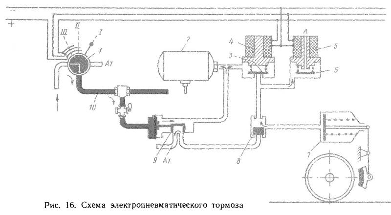
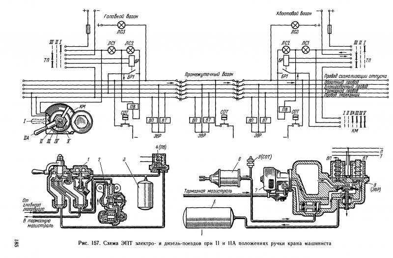
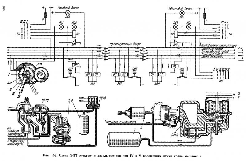
Here is another EPT brakes scheme for You and Cesar to look:
Attached Image: EPT.jpg
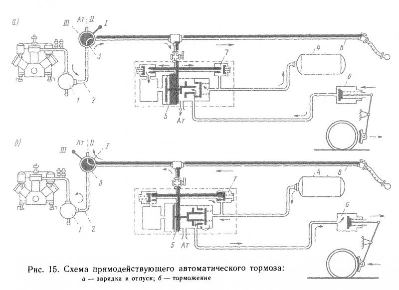
And this is Ari distributor's scheme (not EP), showing, that BP feeds cylyiners and ARs by locomotive's compressor, improving air brakes reliability. Two check-valves are used for that:
Attached Image: distr.jpg

#568 User is offline   darwins 

  • Superintendant
  • Group: Status: Elite Member
  • Posts: 1,252
  • Joined: 25-September 17
  • Gender:Male
  • Simulator:Open Rails
  • Country:

Posted 16 July 2023 - 04:54 AM

That makes the two systems even more similar!

The description on the Hungarian website was

Quote

A szovjet változatot tehát alapvetoen a direkt muködésu ep-fék jelentette. A konstrukció lényege az, hogy a fékhengerek töltése és ürítése az elektromos jel segítségével közvetlenül történik, a kormányszelep megkerülésével, egy légvezetéken keresztül. A kormányszelepnek tehát csak akkor van szerepe, ha az elektromos jel valami miatt kimarad.


Quote

The Soviet version was basically the direct-acting ep-brake. The essence of the construction is that the brake cylinders are filled and emptied directly with the help of the electric signal, by passing the triple valve, through an air line. The triple valve therefore only has a role if the electrical signal is lost for some reason.


So the only real difference then is that the more modern US system is "electronic" and has two-way communication with each car that the driver can view on a screen.
The older Soviet version is based on a more simple electrical connection. So not really any significant difference in an Open Rails model!

#569 User is offline   Weter 

  • Member, Board of Directors
  • PipPipPipPipPipPipPipPipPipPip
  • Group: ET Admin
  • Posts: 7,054
  • Joined: 01-June 20
  • Gender:Not Telling
  • Simulator:ORTS
  • Country:

Posted 16 July 2023 - 05:22 AM

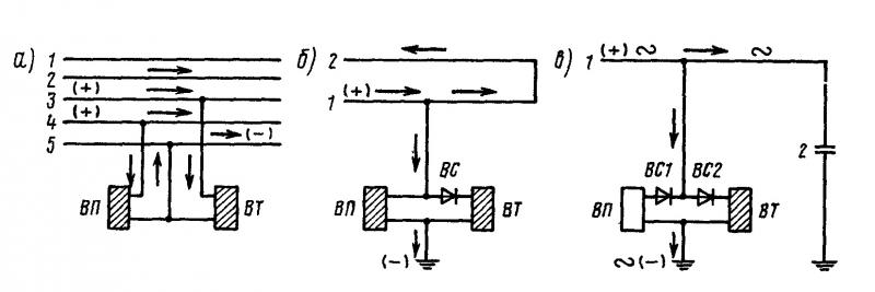
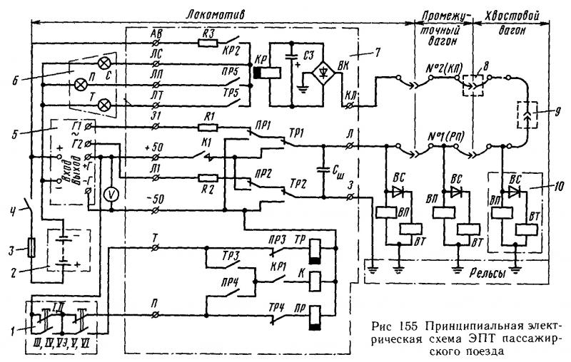
Yes, but the picture shows simplified electric wiring.
There were 1(freight project), 3(passenger) or 5(commuter)-wired systems.
Attached Image: ЭПТ1.jpg
There were control wire in addition, and a workaround to supply distant cars with signal in case of main wire's failure, using reverced polarity.
"Return wire"'s role was played by rails through wheels.
So no yet electronics, but present control and backup.
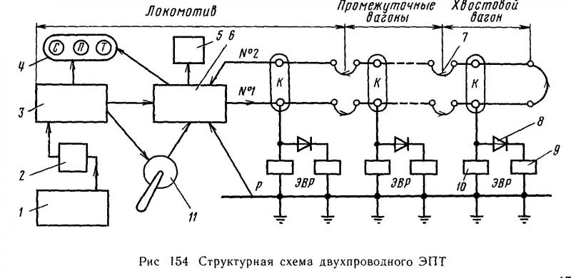
2-wire structure
Attached Image: ЭПТ2.jpg
and principial diagrams
Attached Image: ЭПТ3.jpg
MU trainset's 5-wire scheme, Release and Lap:
Attached Image: ЭПТ5.jpg
EP applcation:
Attached Image: ЭПТ5а.jpg
Based on Westinghouse-design driver's valve with EP electric controller added.

#570 User is offline   darwins 

  • Superintendant
  • Group: Status: Elite Member
  • Posts: 1,252
  • Joined: 25-September 17
  • Gender:Male
  • Simulator:Open Rails
  • Country:

Posted 28 July 2023 - 12:52 PM

View PostJonatan, on 05 July 2023 - 08:51 AM, said:

Over here we had two independent systems. A steam brake for loco wheels only, and vacuum-later-air brake on tender and train only. At a later date some locos had air independent but many kept their steam brake.

I'm also making a tank engine with steam brake for itself, but train air brake only for attached cars, thus the question. At current, steam brake still triggers the air pump, and train brake applies brakes on loco.


I travelled with a British loco equipped with vacuum brake for train and fully independent steam brake for loco today. This was probably more common in UK than I had realised. Three big companies that made their own brake equipment, LNWR, GWR and Midland from early times used a mechanical device to link the steam brake to the vacuum brake. However it seems the smaller companies that used the Gresham and Craven or other manufacturers did not do this. I will try to find out more, but I suspect that the Gresham and Craven method of using the vacuum brake (vacuum) to control the steam brake was not introduced until the 1920s.


  • 68 Pages +
  • « First
  • 55
  • 56
  • 57
  • 58
  • 59
  • Last »
  • You cannot start a new topic
  • You cannot reply to this topic

1 User(s) are reading this topic
0 members, 1 guests, 0 anonymous users