 Log In
 Register Now!
 Help
Help

Through what was explained to me as a freak coincidence of exhaust scavenging, diesel engines fire predictable exhaust pulses that depend on cycle. For example, a two-cycle engine will pulse every revolution, while a four-cycle engine will pulse every other revolution. I've noticed that the way that the ORTS diesel exhaust parameters behave is somewhat predictable, but I would like to know how close my educated guesses are because it's kind of hard to tell by eye:
At first, I suspected the parameters (IdleExhaust and MaxExhaust) were pulses per second, but it seems possibly closer to pulses per 1.5 seconds (( Pulses per minute / 40 ). Ergo, if I need 835 pulses per minute, I should enter a value of (( 835 / 40 ) = 20.875. What is the actual relationship of the number to sprites emitted per minute?
Also, what determines the rate, the raw throttle or engine RPM percent? If it's raw throttle input, then for an engine that idles at 275 RPM, but has Run 1 also at 275 RPM, I would need to enter 4.875 for IdleExhaust if I want the idle pulse to synch in Run 1, and 6.875 if I want the pulses to sync at idle. Conversely, I would simply enter a value of 6.875 if the emission rate is determined by engine RPM percent. It seems to use engine RPM percent, but I'm not quite sure.
Diesel exhaust emitter rate details
Rate Topic:

#1

- Superintendant
-

- Group: Status: Elite Member
- Posts: 1,001
- Joined: 18-July 17
- Gender:Male
- Location:Hastings, MN, US
- Simulator:ORTS
-
Country:

Posted 01 June 2020 - 11:41 PM
#2
- Superintendant
-
- Group: Status: Elite Member
- Posts: 1,842
- Joined: 19-December 09
- Gender:Male
- Location:South of here
- Simulator:ORMG
-
Country:
Posted 02 June 2020 - 03:57 AM
Using the two cycle engine as an example wouldn't a 16 cylinder engine exhaust pulse 16 times per revolution? Once for each cylinder per rev.
Steve
Steve
#3
- Foreman Of Engines
-

- Group: Status: Contributing Member
- Posts: 969
- Joined: 19-December 04
- Gender:Male
- Location:Paris,Ont- Canada
- Simulator:OPEN RAILS & MSTS
-
Country:

Posted 02 June 2020 - 06:21 AM
A 2 cycle fires twice as much as a 4 cycle . If you have multiple cylinders then it depends on how the cylinders are arranged on the crank . They are all going to fire on 1 revolution so in 16 cylinders if they are an even firing or an uneven firing the separation would be between 18 and 22.5 degrees . Take a look at a drawing of the specified engine and look at the journal placement on the crank for the firing order . The less degree separation means a smoother engine . You can find all the good stuff on Wikipedia .
Just thought !
Just thought !
#4
- Superintendant
-
- Group: Status: Elite Member
- Posts: 1,001
- Joined: 18-July 17
- Gender:Male
- Location:Hastings, MN, US
- Simulator:ORTS
-
Country:
Posted 02 June 2020 - 06:58 AM
 steved, on 02 June 2020 - 03:57 AM, said:
Using the two cycle engine as an example wouldn't a 16 cylinder engine exhaust pulse 16 times per revolution? Once for each cylinder per rev.
Steve
Steve
You would think so, and you would think that you would also hear one audible pulse per cylinder, but this is not the case. When I asked about it, I was told that it's probably a consequence of exhaust scavenging. Fun fact: this is how I determine engine RPM when I pitch-correct engine clips. The method is so reliable that I can build a full set of frequency curves for several different blended engine clips with just the raw clips and a table of the engine RPM range. It works on the first try every time.
This clip here provides a really good visual example. You can see that the exhaust streams are not steady, they come in pulses, and when you understand the maximum and minimum RPM values of a given engine, you will find that the pulses come once per engine revolution on a 2-cycle like an EMD, and you'll hear and see the pulses half as often from an Alco or a GE. The GE in that Guilford clip is in Run 7 at 915 RPM, by the way.
#5
- Engineer
-
- Group: Status: Contributing Member
- Posts: 652
- Joined: 10-October 10
- Gender:Male
- Location:Kansas
- Simulator:Open Rails
-
Country:
Posted 02 June 2020 - 12:56 PM
I'll try to add a bit. First, I've yet to completely figure out the relationship between the OR .inc file exhaust parameters and the MSTS .eng file exhaust parameters. There is a relationship there, but no one has explained it fully. Second, it still appears that the relationship between throttle, rpm and exhaust seems to look like this throttle position --> rpm --> exhaust. If that is so, it really isn't right. RPM should be able to--as it does in real life--operate independently of throttle position in some instances (HEP, Automatic Engine-Start Stop--AESS, etc.).
Now, to the questions about 2-cycle vs. 4-cycle. Most of the 2-cycle diesel railroad prime movers out there (and just about all of them in North America) are EMD designs--567, 645, and 710 models. All of those have the common feature of a Roots blower--essentially a supercharger--to pressurize air intake into the cylinders to provide more combustion air and to scavenge exhaust. That scavenging function is probably why exhaust from the EMD's at lower RPMs looks more like a constant stream without a lot of pulsing. EMD also added turbocharging to a number of the models. As RPM would increase and the turbo would spool up, the Roots blower could partially or totally disengage as the turbo would be doing the pressurizing and scavenging. The result would be similar, then, at higher RPMs--mostly a fairly constant stream of exhaust.
4-cycles (GE and Alco, for example) are different than the 2-cycles. In those the upward stroke of the piston on the exhaust stroke scavenges the exhaust gases out of the cylinders. Because the 4-cycle has half the exhaust strokes per cylinder per engine revolution of a 2-cycle, a pulsing effect would be much more noticeable, especially at low RPM's. When turbocharged, a 4-cycle will see an additional effect--smoking exhaust a lower RPMs as the engine is throttled up, due to turbo lag. When fueling is increased faster than the turbo spools up, incomplete combustion caused by temporary over-fueling can make a lot of smoke. This has been reduced in many later model engines with better turbo design, electronic fuel injection and other electronic engine controls.
OR is much better at getting exhaust to "look right" compared to MSTS, but it still is not quite there. In my experimenting, I've found that the "pulsing" effect can be too pronounced, especially in engines that are supposed to smoke less by design. Turbo lag is also not perfectly modeled. In many "real" locomotives there is an "inverse" effect of turbo lag smoke--that is, the engine will smoke profusely when coming off of idle, with the amount of turbo lag smoke decreasing with each additional notch of throttle up. This would be logical, as the turbo is already partially spun-up as each additional notch-out is made in the throttle.
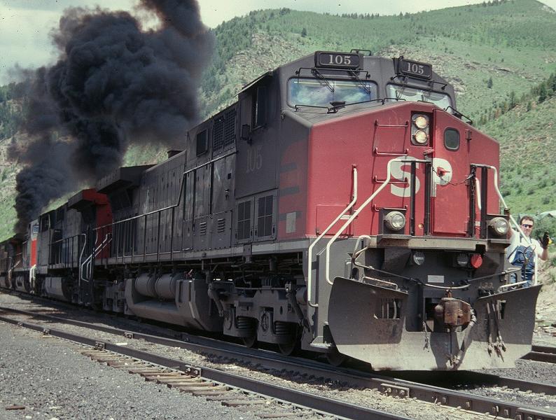
If you want to see what serious turbo lag and over-fueling looks like in a 4-cycle prime mover, here's example from 1996 with an SP AC4400. They hadn't quite gotten the EFI calibrated correctly. Just as the locomotive passed me after this photo, the engineer cracked the throttle from Notch 2 to Notch 4 and the bottom portion of that smoke cloud ignited from the hotter gases coming up the stack--a flame about 4' tall out of the stack was a result. I missed getting a photo of that. As he notched out again (to Run 6), there was some more smoke, but much less than at the start. For the record, this was taken at Minturn, CO at the foot of the grade ascending Tennessee Pass. These are the manned "swing" helpers being added at mid-train of a heavy eastbound coal load. The helpers have coupled to the rear cut of cars and are now starting to pull the rear part of the train up to a coupling with front half. The brakeman is directing the move from the step. The engineer is on the rear locomotive of the swing helper set, actually running in reverse. He was there, so that when the swing helpers were cut off at the summit to return west to Minturn, he would be on the then lead locomotive.
Now, to the questions about 2-cycle vs. 4-cycle. Most of the 2-cycle diesel railroad prime movers out there (and just about all of them in North America) are EMD designs--567, 645, and 710 models. All of those have the common feature of a Roots blower--essentially a supercharger--to pressurize air intake into the cylinders to provide more combustion air and to scavenge exhaust. That scavenging function is probably why exhaust from the EMD's at lower RPMs looks more like a constant stream without a lot of pulsing. EMD also added turbocharging to a number of the models. As RPM would increase and the turbo would spool up, the Roots blower could partially or totally disengage as the turbo would be doing the pressurizing and scavenging. The result would be similar, then, at higher RPMs--mostly a fairly constant stream of exhaust.
4-cycles (GE and Alco, for example) are different than the 2-cycles. In those the upward stroke of the piston on the exhaust stroke scavenges the exhaust gases out of the cylinders. Because the 4-cycle has half the exhaust strokes per cylinder per engine revolution of a 2-cycle, a pulsing effect would be much more noticeable, especially at low RPM's. When turbocharged, a 4-cycle will see an additional effect--smoking exhaust a lower RPMs as the engine is throttled up, due to turbo lag. When fueling is increased faster than the turbo spools up, incomplete combustion caused by temporary over-fueling can make a lot of smoke. This has been reduced in many later model engines with better turbo design, electronic fuel injection and other electronic engine controls.
OR is much better at getting exhaust to "look right" compared to MSTS, but it still is not quite there. In my experimenting, I've found that the "pulsing" effect can be too pronounced, especially in engines that are supposed to smoke less by design. Turbo lag is also not perfectly modeled. In many "real" locomotives there is an "inverse" effect of turbo lag smoke--that is, the engine will smoke profusely when coming off of idle, with the amount of turbo lag smoke decreasing with each additional notch of throttle up. This would be logical, as the turbo is already partially spun-up as each additional notch-out is made in the throttle.
If you want to see what serious turbo lag and over-fueling looks like in a 4-cycle prime mover, here's example from 1996 with an SP AC4400. They hadn't quite gotten the EFI calibrated correctly. Just as the locomotive passed me after this photo, the engineer cracked the throttle from Notch 2 to Notch 4 and the bottom portion of that smoke cloud ignited from the hotter gases coming up the stack--a flame about 4' tall out of the stack was a result. I missed getting a photo of that. As he notched out again (to Run 6), there was some more smoke, but much less than at the start. For the record, this was taken at Minturn, CO at the foot of the grade ascending Tennessee Pass. These are the manned "swing" helpers being added at mid-train of a heavy eastbound coal load. The helpers have coupled to the rear cut of cars and are now starting to pull the rear part of the train up to a coupling with front half. The brakeman is directing the move from the step. The engineer is on the rear locomotive of the swing helper set, actually running in reverse. He was there, so that when the swing helpers were cut off at the summit to return west to Minturn, he would be on the then lead locomotive.
Attached thumbnail(s)
#6
- Executive Vice President
-

- Group: ET Admin
- Posts: 4,862
- Joined: 07-February 13
- Gender:Male
- Location:Leoben, Styria, Austria, Europe
- Simulator:ORTS / MSTS
-
Country:

Posted 02 June 2020 - 02:23 PM
Wow, Wade, thank you for the great explanations (and the cool photo)!
I wish I had known just half of this back when I did my experiments to find out good values to publish with my Diesel Power Updater (DPU) program...
Cheers, Markus
I wish I had known just half of this back when I did my experiments to find out good values to publish with my Diesel Power Updater (DPU) program...
Cheers, Markus
#7
- Superintendant
-
- Group: Status: Elite Member
- Posts: 1,001
- Joined: 18-July 17
- Gender:Male
- Location:Hastings, MN, US
- Simulator:ORTS
-
Country:
Posted 02 June 2020 - 03:42 PM
With the exception of the UP GP9 experiment, turbocharged EMD locomotives do not use roots blowers, the turbo runs on an overspeed clutch up to about Run 7 or so, except under conditions of high load. The 645 was the last EMD engine to be offered with a roots blower.
On the subject of throttle sequencing, when doing the full diesel block is unfeasible or undesirable, you can insert a bare-bones OR diesel engine block that only modifies the throttle schedule. I am in the final stages of testing a conversion kit for the SLI GP9s that does exactly that, as well as fixes the dynamic range - or lack thereof - of the audio.
On the subject of throttle sequencing, when doing the full diesel block is unfeasible or undesirable, you can insert a bare-bones OR diesel engine block that only modifies the throttle schedule. I am in the final stages of testing a conversion kit for the SLI GP9s that does exactly that, as well as fixes the dynamic range - or lack thereof - of the audio.
#8
- Engineer
-
- Group: Status: Contributing Member
- Posts: 652
- Joined: 10-October 10
- Gender:Male
- Location:Kansas
- Simulator:Open Rails
-
Country:
Posted 02 June 2020 - 05:30 PM
Erick is correct about the Roots blower only being used on non-turbocharged EMD 2-cycle prime movers, HOWEVER, names aside, the "turbocharger" used on the 645 and 710 models is a clutched design that essentially functions as a "blower" (supercharger) at low engine RPM, with the clutch disengaging as engine RPM reaches sufficient turbocharger boost to negate the need for supercharging. It's a novel design, but the overall exhaust effect would still, I believe, be pretty similar to a Roots blower-equipped non-turbo'ed 2 cycle prime mover.
By the way, the Roots blower was used on millions of GM Detroit Diesel 2-cycle diesel engines used in equipment, trucks, and marine applications from the late 1930's until the late 1990's. They were durable, easily rebuilt engines and many of them are still in service, including in a lot of on-track railroad MOW equipment. Called "Screamin' Jimmies" because of their loud exhaust, they were liked for their reliability, longevity, and good power-to-weight ratio. They did have their quirks. The "Detroits" were--as noted--loud, and they--because of their 2-stroke design--had somewhat higher emissions than many 4-stroke designs. Unlike their big brother EMD prime movers, the Detroits did not like to be idled for any extended period. If not idled at something in excess of 1/3 throttle, they would have issues like oil seal problems, among others. The Detroit 2-cycles often had chronic oil leaks, garnering the nickname of "Drip-troit" among many diesel users. The old, but pretty true joke was that Detroit 2-strokes were best run only two ways--wide open or off. I haven't researched to see how the engineers at GM designed the EMD 2-strokes to tolerate extended idling, but they did manage it somehow.
By the way, the Roots blower was used on millions of GM Detroit Diesel 2-cycle diesel engines used in equipment, trucks, and marine applications from the late 1930's until the late 1990's. They were durable, easily rebuilt engines and many of them are still in service, including in a lot of on-track railroad MOW equipment. Called "Screamin' Jimmies" because of their loud exhaust, they were liked for their reliability, longevity, and good power-to-weight ratio. They did have their quirks. The "Detroits" were--as noted--loud, and they--because of their 2-stroke design--had somewhat higher emissions than many 4-stroke designs. Unlike their big brother EMD prime movers, the Detroits did not like to be idled for any extended period. If not idled at something in excess of 1/3 throttle, they would have issues like oil seal problems, among others. The Detroit 2-cycles often had chronic oil leaks, garnering the nickname of "Drip-troit" among many diesel users. The old, but pretty true joke was that Detroit 2-strokes were best run only two ways--wide open or off. I haven't researched to see how the engineers at GM designed the EMD 2-strokes to tolerate extended idling, but they did manage it somehow.
#9
- Superintendant
-
- Group: Status: Elite Member
- Posts: 1,001
- Joined: 18-July 17
- Gender:Male
- Location:Hastings, MN, US
- Simulator:ORTS
-
Country:
Posted 03 June 2020 - 01:34 AM
I haven't read this whole paper, as I primarily used it for the engine data, so the answer may very well be contained here.
This video also offers interesting insight into the development of GM's 2-stroke diesels.
This video also offers interesting insight into the development of GM's 2-stroke diesels.
#10
- Member, Board of Directors
-
- Group: ET Admin
- Posts: 6,888
- Joined: 01-June 20
- Gender:Not Telling
- Simulator:ORTS
-
Country:

Posted 08 June 2020 - 12:46 PM
As I understand, the position of throttle handle more likely gives POWER reference for Diesel set, not rpm, when reverser isn't at 0 position.
Because there's complex Power-regulating system between Engineer`s controller and high pressure fuel-injecting pump in powerful locos.
So, when load rapidly rises, the RPM drops, but at the same time the exaltation of Main Generator is increased by the systrm, so DG-set gives more current (mean-more power) to traction motors. And opposite, when load drops, exaltation lowers automaticaly, but rpm rises a little, and then fuel quantity is reduced by regulator, trying to maintain defined rotation speed.
Making black clouds, when rising up calls "Loko Gived a bear" among staff in some countries.