 Log In
 Register Now!
 Help
Help

Looks great, kudos to you for the awesome work in figuring this out! :good2:
Cheers, Markus
Digital LED Speedometer
Rate Topic:

#11

- Executive Vice President
-

- Group: ET Admin
- Posts: 4,862
- Joined: 07-February 13
- Gender:Male
- Location:Leoben, Styria, Austria, Europe
- Simulator:ORTS / MSTS
-
Country:

Posted 22 October 2020 - 02:05 PM
#12
- Conductor
-

- Group: Status: Active Member
- Posts: 268
- Joined: 15-March 20
- Gender:Male
- Location:Barcelona, Catalunya
- Simulator:Open Rails
-
Country:

Posted 22 October 2020 - 05:07 PM
 markus_GE, on 22 October 2020 - 02:05 PM, said:
Looks great, kudos to you for the awesome work in figuring this out! :good2:
Cheers, Markus
Cheers, Markus
Thank you Markus! I will also write here a little more about the procedure I followed to do this, which was not easy, it was necessary to use the mind to find a method that can serve quite well:
Indeed, they are several objects.
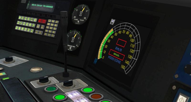
On the one hand, there is SPEEDOMETER:0:0 which is the speedometer itself and it is kept hidden under the main cover that is under the speedometer and that is a static piece.
This piece, when it starts turning, does it from its center, but as it is short, it needs SPEEDOMETER:0:1, 0:2, etc. to finish the circle. These pieces do not turn, and they are kept behind the speedometer (not the cover but behind the whole), instead of turning, they appear in their position by moving in the frame where the speedometer is already incomplete.
Then, to convert all the pieces in a kind of individual leds, you need another piece with transparencies that includes the lines to divide the "bars" that form the speedometer itself. This piece is also totally static.
In addition, the pieces that make up the speedometer have HalfBright mode to glow in the dark.
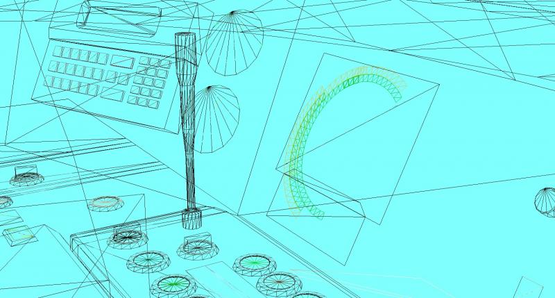
I put two images to help you see all this. The second one shows the pieces in grid, maybe it will help you to understand better the matter. I hope it will be useful for all!
#13
- Conductor
-
- Group: Status: Active Member
- Posts: 268
- Joined: 15-March 20
- Gender:Male
- Location:Barcelona, Catalunya
- Simulator:Open Rails
-
Country:
Posted 06 November 2020 - 04:55 PM
Continuing with the issue of digital displays in 3d cabs, i find a new problem.
I try to simply create two SPEEDOMETER displays that show the same (i.e. the speed in KM hour), but there is no way. I can only declare one display.
I have already tried everything:
SPEEDOMETER:0:0, 0:1, etc.
SPEEDOMETER:1:0, 1:1, etc.
Nothing works. In fact, in some cases, when you declare a second SPEEDOMETER, the first one disappears from the view. It does not occur to me anymore what can happen.
If somebody has a cabin 3D with 2 SPEEDOMETERS digitals working, we would thank him/her to tell us a little their experience.
Thank you very much!
#14
- Engineer
-

- Group: Status: Contributing Member
- Posts: 501
- Joined: 28-June 08
- Location:Perth, WA
-
Country:

Posted 06 November 2020 - 08:45 PM
With the object names for digital displays, the first number references which speedometer gauge in the CVF file to get details from like type of gauge and units. The second number is only for digital gauges and tells OR which font size to use in the 3D cabview.
I have just tested with 3 digital speedometer objects and an animated needle object called:
SPEEDOMETER:0:20
SPEEDOMETER:1:30
SPEEDOMETER:2:42
SPEEDOMETER:3
In the CFV file I have 3 Digital and 1 Dial Speedometers with the following values and in this order:
Digital (
Type ( SPEEDOMETER DIGITAL )
Position ( 365 53 32 16 )
ScaleRange ( 0 200 )
Accuracy ( 1 )
AccuracySwitch ( 10 )
LeadingZeros ( 0 )
Justification ( 1 )
PositiveColour ( 2
ControlColour ( 15 15 15 )
SwitchVal ( 75 )
ControlColour ( 0 0 0 )
)
NegativeColour ( 0 )
DecreaseColour ( 0 )
Units ( MILES_PER_HOUR )
)
Digital (
Type ( SPEEDOMETER DIGITAL )
Position ( 3000 3000 32 16 )
ScaleRange ( 0 200 )
Accuracy ( 1 )
AccuracySwitch ( 10 )
LeadingZeros ( 0 )
Justification ( 1 )
PositiveColour ( 2
ControlColour ( 15 15 15 )
SwitchVal ( 75 )
ControlColour ( 0 0 0 )
)
NegativeColour ( 0 )
DecreaseColour ( 0 )
Units ( KM_PER_HOUR )
)
Digital (
Type ( SPEEDOMETER DIGITAL )
Position ( 365 53 32 16 )
ScaleRange ( 0 200 )
Accuracy ( 1 )
AccuracySwitch ( 10 )
LeadingZeros ( 0 )
Justification ( 1 )
PositiveColour ( 2
ControlColour ( 15 15 15 )
SwitchVal ( 75 )
ControlColour ( 0 0 0 )
)
NegativeColour ( 0 )
DecreaseColour ( 0 )
Units ( MILES_PER_HOUR )
)
Dial (
Type ( SPEEDOMETER DIAL )
Position ( 365 24 32 64 )
Graphic ( "..\\..\\Common.Cab\\EMD\\needlegrn.ace" )
Style ( POINTER )
ScaleRange ( 0 80 )
ScalePos ( 220 140 )
Units ( MILES_PER_HOUR )
Pivot ( 28 )
DirIncrease ( 0 )
)
So in the 3D cab I have 3 digital speedometers and a analogue needle speedometer displayed and all function.
SPEEDOMETER:0:20 will display MPH at font size 20
SPEEDOMETER:1:30 will display KPH at font size 30
SPEEDOMETER:2:42 will display MPH at font size 42
SPEEDOMETER:3 is an animated needle over a dial
As I don't want the MPH to be visible in my 2D view, the second SPEEDOMETER in the CVF file has the first 2 values in position as 3000 3000. This will display this gauge 4000 pixels to the right and 4000 pixels down from the top left corner of the screen so will not be visible on UHD monitor.
Hope this helps.
Cheers,
Marek.
#15
- Conductor
-
- Group: Status: Active Member
- Posts: 268
- Joined: 15-March 20
- Gender:Male
- Location:Barcelona, Catalunya
- Simulator:Open Rails
-
Country:
Posted 07 November 2020 - 10:55 AM
Thank you very much Marek.
Yes, you have been very helpful. The thing is that, besides the two Digital SPEEDOMETERS, I have others that are needles, shaped like a led indicator.
SPEEDOMETER:0:14 was the digital numeric one that was already working.
The rest, SPEEDOMETER:1:0, 1:1, 1:2, were the Dials.
Then, the other digital one, had it as SPEEDOMETER:2:12. Until I have exported it as SPEEDOMETER:4:12, the numbers have not appeared.
Now, a new problem. I have the first Digital (SPEEDOMETER:0:14) with the texture speed.ace and alert.ace. But also a SPEEDLIM_DISPLAY:0:12 with the texture speedlim.ace it turns out now that the SPEEDOMETER:4:12, uses as texture speedlim.ace, and this does not interest me for the color. Any ideas? Thanks a lot!
#16
- Conductor
-
- Group: Status: Active Member
- Posts: 268
- Joined: 15-March 20
- Gender:Male
- Location:Barcelona, Catalunya
- Simulator:Open Rails
-
Country:
Posted 08 November 2020 - 11:32 AM
Hello!
I have found another method to animate this other type of speed and target speed indicators in 3d cabs for these cases where needles cannot be placed (shaped like a strip of led indicators):
In this case, each led is a separate piece. In this, as shown in 5 km segments, they are not too many.
You have to build the whole piece, place and cut sections it into separate planes to control them independently. The code for the inner sector, green, which shows the real speed, is as follows:
This code is referred to in the special cvf for the 3d cabin. For this reason, the .ace graphic is referred to outside the screen, although a transparent one can also be used.
Each of the parts in the 3d cabin model is called SPEEDOMETER:0:0, SPEEDOMETER:0:1, SPEEDOMETER:0:2 etc. up to a total of 24, i.e. the last one is called SPEEDOMETER:0:23.
The pieces (leds) need a complete animation of the 24 frames, in which the frame 0 shows them hidden behind the panel and in their respective frame they advance in front to be shown.
This is the animation for the piece SPEEDOMETER:0:0
The movement in both X and Y is irrelevant, that's why it is shown here like this. The movement in Z represents the backward movement from Frame 0 to Frame 1, and the plane represented by the led will remain there until the train stops completely, at which time it will be hidden again.
The code of the animation of the last object, SPEEDOMETER:0:23 is the following:
That is, it is only shown in the last frame, and as soon as the speed is less than 115, it will be hidden. Naturally, each of the intermediate pieces has its own animation, which increases in number, always with its last frame in the visible position.
Another interesting thing is that the model does not need to have 25 Frames in the Project Properties. Having 9 is enough to make it work.
And for the yellow external indicator (target speed), everything is exactly the same except the fact that you still need its code in the .cvf file:
...and the names of the pieces that compose it are SPEED_PROJECTED:0:0, 0:1, 0:2, etc.
Well, I hope this helps to clarify more things and that it is useful to advance in the representation of 3D cabins. I will never keep for myself the knowledge acquired through help, logic, trial and error.
I have found another method to animate this other type of speed and target speed indicators in 3d cabs for these cases where needles cannot be placed (shaped like a strip of led indicators):
In this case, each led is a separate piece. In this, as shown in 5 km segments, they are not too many.
You have to build the whole piece, place and cut sections it into separate planes to control them independently. The code for the inner sector, green, which shows the real speed, is as follows:
Dial (
			Type ( SPEEDOMETER DIAL )
			Position ( 691 317 66 66 )
			Graphic ( "MMS6000agujavolts.ace" )
			Style ( POINTER )
			ScaleRange ( 0 120 )
			ScalePos ( 0 15 )
			Units ( KM_PER_HOUR )
			Pivot ( 0 )
			DirIncrease ( 0 )
		)
This code is referred to in the special cvf for the 3d cabin. For this reason, the .ace graphic is referred to outside the screen, although a transparent one can also be used.
Each of the parts in the 3d cabin model is called SPEEDOMETER:0:0, SPEEDOMETER:0:1, SPEEDOMETER:0:2 etc. up to a total of 24, i.e. the last one is called SPEEDOMETER:0:23.
The pieces (leds) need a complete animation of the 24 frames, in which the frame 0 shows them hidden behind the panel and in their respective frame they advance in front to be shown.
This is the animation for the piece SPEEDOMETER:0:0
0:X;Y;8.2054;
1:X;Y;8.2032;
The movement in both X and Y is irrelevant, that's why it is shown here like this. The movement in Z represents the backward movement from Frame 0 to Frame 1, and the plane represented by the led will remain there until the train stops completely, at which time it will be hidden again.
The code of the animation of the last object, SPEEDOMETER:0:23 is the following:
0:X;Y;8.2054;
1:X;Y;8.2054;
2:X;Y;8.2054;
3:X;Y;8.2054;
4:X;Y;8.2054;
5:X;Y;8.2054;
6:X;Y;8.2054;
7:X;Y;8.2054;
8:X;Y;8.2054;
9:X;Y;8.2054;
10:X;Y;8.2054;
11:X;Y;8.2054;
12:X;Y;8.2054;
13:X;Y;8.2054;
14:X;Y;8.2054;
15:X;Y;8.2054;
16:X;Y;8.2054;
17:X;Y;8.2054;
18:X;Y;8.2054;
19:X;Y;8.2054;
20:X;Y;8.2054;
21:X;Y;8.2054;
22:X;Y;8.2054;
23:X;Y;8.2032;
That is, it is only shown in the last frame, and as soon as the speed is less than 115, it will be hidden. Naturally, each of the intermediate pieces has its own animation, which increases in number, always with its last frame in the visible position.
Another interesting thing is that the model does not need to have 25 Frames in the Project Properties. Having 9 is enough to make it work.
And for the yellow external indicator (target speed), everything is exactly the same except the fact that you still need its code in the .cvf file:
Dial (
			Type ( SPEED_PROJECTED DIAL )
			Position ( 691 317 66 66 )
			Graphic ( "MMS6000agujavolts.ace" )
			Style ( POINTER )
			ScaleRange ( 0 120 )
			ScalePos ( 0 15 )
			Units ( KM_PER_HOUR )
			Pivot ( 0 )
			DirIncrease ( 0 )
		)
...and the names of the pieces that compose it are SPEED_PROJECTED:0:0, 0:1, 0:2, etc.
Well, I hope this helps to clarify more things and that it is useful to advance in the representation of 3D cabins. I will never keep for myself the knowledge acquired through help, logic, trial and error.
#17
- Hostler
-
- Group: Status: Fired
- Posts: 51
- Joined: 28-February 19
- Gender:Male
- Simulator:Open rails
-
Country:

Posted 28 December 2020 - 01:14 PM
Awesome feature! It's possible to do the same kind of display in 2D cabs? I have a cab that i need to do the circular gauge for ammeter and speedometer.
#18
- Executive Vice President
-
- Group: ET Admin
- Posts: 4,862
- Joined: 07-February 13
- Gender:Male
- Location:Leoben, Styria, Austria, Europe
- Simulator:ORTS / MSTS
-
Country:
Posted 29 December 2020 - 04:00 PM
hugoakio, on 28 December 2020 - 01:14 PM, said:
Awesome feature! It's possible to do the same kind of display in 2D cabs? I have a cab that i need to do the circular gauge for ammeter and speedometer.
Yes, see posts #2 to #4 in the above. I'll have to look for details, (not today anymore, though).
Cheers, Markus