 Log In
 Register Now!
 Help
Help

After much reading, I've figured out that "taper" refers to the slope of the curve. Also, a system wherein the dynamic brake is dependent upon the controller AND the speed.
So how does one find the taper speed?...in the spreadsheet as provided the taper speed is 1 mph, I looked in all sorts of threads and corners of the web and cannot find specific references to taper speeds for individual locomotives.
Also, pardon all my questions, I know much of this is known to many in these parts...I found threads from 2005 over at TS where all you folks were hashing out MSTS and dynamic brakes.
Even found and downloaded Peter Baker's two dynamic brake physics files in the library, interesting stuff...but I did not see ( maybe missed it ) a reference to taper speed. Also none, that I could find in the MSTS eng files.
Still reading the pdf and working the spreadsheet, Gerry
Guideline For Setting Open Rails Braking Parameters (Including Blended Braking)
Rate Topic:

#21

- Executive Vice President
-

- Group: ET Admin
- Posts: 3,438
- Joined: 14-March 13
- Gender:Male
- Location:known universe
- Simulator:Open Rails
-
Country:

Posted 25 April 2019 - 06:50 PM
#22
- Open Rails Developer
-

- Group: Status: Elite Member
- Posts: 1,889
- Joined: 24-June 11
- Gender:Male
-
Country:

Posted 25 April 2019 - 08:16 PM
Genma Saotome, on 25 April 2019 - 08:03 AM, said:
IMO MaxReleaseRate (6) is too low.
The reason that I suggest this is that there are three components that need to be considered when looking at a brake system.
These are as follows:
i) Wagon equipment - typically the BC is connected to a reservoir, and therefore changes in pressure will occur reasonably rapidly - ie < 1-2 secs. This section is covered by the code in the wagon section, ie MaxReleaseRate, MaxApplicationRate, etc.
ii) Locomotive Control Equipment - this typically includes the equalising reservoir and the drivers control valve. This equipment provides the "reference signal" to the brake pipe. Typically changes in this equipment would be slower to allow the driver some level of realistic control over the braking pressure. These values could be somewhere between 5 - 20 psi/sec, depending upon the desired responsiveness. This section is covered by the code in the engine section, ie TrainBrakesControllerMaxApplicationRate, TrainBrakesControllerMaxReleaseRate, etc.
iii) Brake Pipe - is the signalling mechanism used in pure airbrakes. As the brakes are released and applied there will be a gradient delay along the length of the train as the pressure in the brake pipe increases or decreases in pressure. This thus introduces another significant delay mechanism in brake operation. This section is modelled by the ORTSBrakePipeChargingRate, TrainPipeLeakRate, etc.
Thus most of the delay in brake operation is in items ii) and iii) above.
For example most of the delay in applying a brake will be the time that the driver takes to release air pressure in the BP, and for the change to propagate along the BP.
OR, in the air brake code, at the moment does model the change in delay times due to the length of the train. This was implemented into Vacuum braking, but has not been carried across into air brakes yet.
This publication shows some of the overall times to apply the brakes in a full service and emergency brake application. Whilst it is somewhat old, the time values would still be within the same level of expectation for more modern braking.
#23
- Fireman
-

- Group: Status: Active Member
- Posts: 178
- Joined: 13-December 09
- Gender:Male
-
Country:
Posted 25 April 2019 - 09:27 PM
R H Steele, on 25 April 2019 - 06:50 PM, said:
After much reading, I've figured out that "taper" refers to the slope of the curve. Also, a system wherein the dynamic brake is dependent upon the controller AND the speed.
So how does one find the taper speed?...in the spreadsheet as provided the taper speed is 1 mph, I looked in all sorts of threads and corners of the web and cannot find specific references to taper speeds for individual locomotives.
Also, pardon all my questions, I know much of this is known to many in these parts...I found threads from 2005 over at TS where all you folks were hashing out MSTS and dynamic brakes.
Even found and downloaded Peter Baker's two dynamic brake physics files in the library, interesting stuff...but I did not see ( maybe missed it ) a reference to taper speed. Also none, that I could find in the MSTS eng files.
Still reading the pdf and working the spreadsheet, Gerry
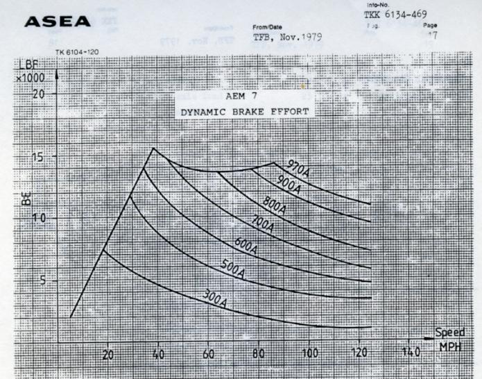
In that spreadsheet the slope is controlled mostly by the maximum dynamic brake power parameter. The taper value just refers to how many MPH it takes to go from the constant HP portion of the curve at high speeds down to zero. In this case I put in a very abrupt change of only 1 mph because the AEM-7 locomotive can't operate at much over 125 mph. Therefore, it made no sense to specify the dynamic brake curve much past about 135 mph as the locomotive can't reach those speeds anyway.
In some cases the taper value can be used to duplicate real world behavior but its primary function in that spreadsheet is to just cut off the dynamic brake function at some speed above the top speed of the locomotive.
#24
- Executive Vice President
-
- Group: ET Admin
- Posts: 3,438
- Joined: 14-March 13
- Gender:Male
- Location:known universe
- Simulator:Open Rails
-
Country:
Posted 25 April 2019 - 10:56 PM
I'm working late, just finished first set of working curves. Now my experience is limited...but these sure seem like a huge improvement over using the default MSTS parameters.
Attached is the C40-8 include engine file and a copy of the spreadsheet. Apologies for making some format changes to the curve set portion of the spreadsheet. I used 80mph as the taper speed, because the top speed of the C40-8 is given as 73. I used Bob Boudoin's C40-8 eng physics file. http://www.elvastower.com/forums/public/style_emoticons/default/Neeeedsleeep.gifgood night.
Attached is the C40-8 include engine file and a copy of the spreadsheet. Apologies for making some format changes to the curve set portion of the spreadsheet. I used 80mph as the taper speed, because the top speed of the C40-8 is given as 73. I used Bob Boudoin's C40-8 eng physics file. http://www.elvastower.com/forums/public/style_emoticons/default/Neeeedsleeep.gifgood night.
Attached File(s)
-
 DynamicBrakeCurves.zip (41.63K)
Number of downloads: 535
#25
- Fireman
-
- Group: Status: Active Member
- Posts: 178
- Joined: 13-December 09
- Gender:Male
-
Country:
Posted 25 April 2019 - 11:37 PM
R H Steele, on 25 April 2019 - 10:56 PM, said:
I'm working late, just finished first set of working curves. Now my experience is limited...but these sure seem like a huge improvement over using the default MSTS parameters.
Attached is the C40-8 include engine file and a copy of the spreadsheet. Apologies for making some format changes to the curve set portion of the spreadsheet. I used 80mph as the taper speed, because the top speed of the C40-8 is given as 73. I used Bob Boudoin's C40-8 eng physics file. http://www.elvastower.com/forums/public/style_emoticons/default/Neeeedsleeep.gifgood night.
Attached is the C40-8 include engine file and a copy of the spreadsheet. Apologies for making some format changes to the curve set portion of the spreadsheet. I used 80mph as the taper speed, because the top speed of the C40-8 is given as 73. I used Bob Boudoin's C40-8 eng physics file. http://www.elvastower.com/forums/public/style_emoticons/default/Neeeedsleeep.gifgood night.
Just to clarify how the taper parameter works, if you set it for 80 mph then it tapers off the dynamic braking from whatever it is at the max speed ( 26 mph in your case ) to zero over an 80 mph range. That's why it doesn't fall to zero until 106 mph. The other thing is when you taper over a very large range the dynamic braking curve in that range is no longer constant HP. It could be increasing HP or decreasing HP. This may or may not be realistic for any particular locomotive. When I don't have any data, I would just assume constant HP once you're past the flat portion of the dynamic brake curve. You might try something like 70 for the max speed, then something low for the taper, like 10 mph.
Dynamic braking curves can actually get fairly complex. Here's the one for the AEM7-DC:
I couldn't use a spreadsheet for that one. I just had to manually tabulate the data points and put them into the proper format for the ORTSDynamicBrakeForceCurves.
Attached thumbnail(s)
#26
- Foreman Of Engines
-

- Group: Status: Contributing Member
- Posts: 998
- Joined: 13-June 15
- Gender:Male
- Simulator:MSTS
-
Country:

Posted 26 April 2019 - 03:54 AM
Hi
The Amtrak dual brake PDF is very informative. UK MU Disc brake stock full service deceleration at 48PSI is 2MPHPS. However this deceleration appears constant to around 20mph, where it rise to 2.5MPHPS.
The "instantaneous deceleration MPHPS" charts are very rare to find. You wouldn't happen to have these charts for tread-brake only stock?
On your own brake guideline PDF, is the empty wagon 38% brake ratio for composite shoes and cast-iron shoes?
Thanks
#27
- Fireman
-
- Group: Status: Active Member
- Posts: 178
- Joined: 13-December 09
- Gender:Male
-
Country:
Posted 26 April 2019 - 08:52 AM
Coolhand101, on 26 April 2019 - 03:54 AM, said:
Hi
The Amtrak dual brake PDF is very informative. UK MU Disc brake stock full service deceleration at 48PSI is 2MPHPS. However this deceleration appears constant to around 20mph, where it rise to 2.5MPHPS.
The "instantaneous deceleration MPHPS" charts are very rare to find. You wouldn't happen to have these charts for tread-brake only stock?
Thanks
Yes, the paper was a very valuable resource helping me tweak the braking rates. They also gave stopping distances from various speeds which helped me to validate my settings.
The Amfleet coaches as delivered had disc brakes only. They were modified by adding tread brakes to the disc brakes. I think the final setup was 60% disc/40% tread braking. They never had tread brakes only. My guess is if they had tread brakes only the primary difference would be that the deceleration rates would have started increasing at a much lower value than with disc brakes.
Quote
On your own brake guideline PDF, is the empty wagon 38% brake ratio for composite shoes and cast-iron shoes?
I assumed composite shoes. Guidelines for cast iron shoes often assumed a 50% brake ratio because of the lower coefficient of friction. Note that a 38% brake ratio and an average CoF of 0.3 for composite shoes would give an average deceleration rate of roughly 2.5 mph/sec. However, the 38% ratio typically applies mostly to empty freight stock. The idea is to have the brakes as strong as possible but still not have wheel slide when the car is unloaded. Some freight cars have load sensors which apply a lower brake pressure when the car is empty. This lets you have higher deceleration rates when loaded but still avoid sliding the wheels when unloaded.
#28
- Executive Vice President
-
- Group: ET Admin
- Posts: 3,438
- Joined: 14-March 13
- Gender:Male
- Location:known universe
- Simulator:Open Rails
-
Country:
Posted 26 April 2019 - 11:09 AM
Re: taper speed and complexity of curves: Yes I see. All this information will take time to digest and integrate. I'm most definitely in the "simple" curve phase. Looking for Dynamic brake values that give better performance in OR. The interesting thing about OR is that as one learns more about the physics -- progressing from a less complex knowledge base to more complex ( like yours and the other knowledgeable posters in this thread ) you can use that knowledge to create, for yourself, a better experience in OR.
Thank you for your kind attention and help,Gerry
Thank you for your kind attention and help,Gerry
#29
- Fireman
-
- Group: Status: Active Member
- Posts: 178
- Joined: 13-December 09
- Gender:Male
-
Country:
Posted 26 April 2019 - 11:15 AM
All very true. Also, I find that the hardest part of recreating more realistic performance isn't tweaking parameters but researching what that performance should be. Unless you've ridden on or driven a particular type of train, you're really just guestimating how it should perform without hard data.
#30
- Open Rails Developer
-
- Group: Status: Elite Member
- Posts: 5,490
- Joined: 30-June 10
- Gender:Not Telling
- Simulator:Open Rails
-
Country:
Posted 26 April 2019 - 01:48 PM
jtr1962, on 25 April 2019 - 09:07 AM, said:
That brings me to another thing I wish the Open Rails programming team would implement. A lot of people run both freight and passenger trains. For freight trains unchecking the Graduated Release Air Brakes box gives correct operation. For passenger trains the box needs to be checked. There should be a parameter in the .eng file which overrides this setting so you don't have to check it or uncheck every time you switch from passenger to freight. I suggest something like ORTSGraduatedReleaseAirBrakes. You would use ORTSGraduatedReleaseAirBrakes ( 0 ) for freight locomotives and ORTSGraduatedReleaseAirBrakes ( 1 ) for passenger locomotives.
If there's no existing MSTS parameter for this, we absolutely should add it. Thanks for the Trello card!