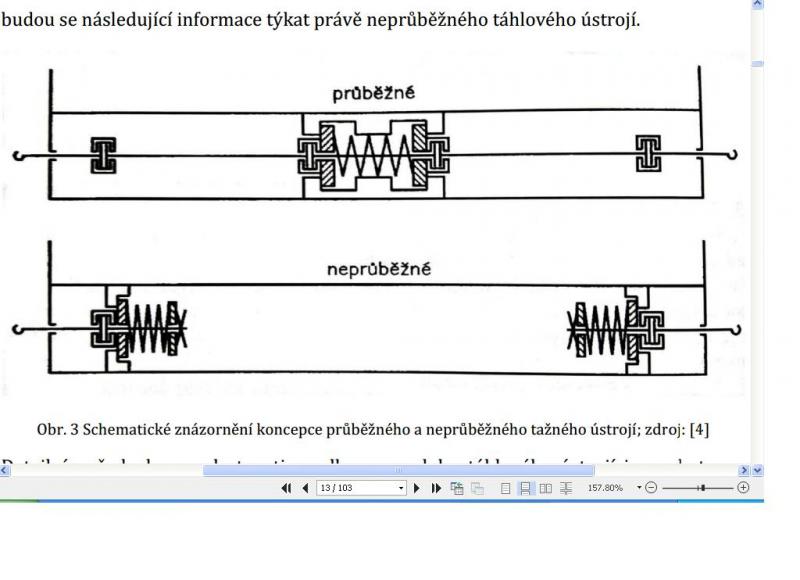
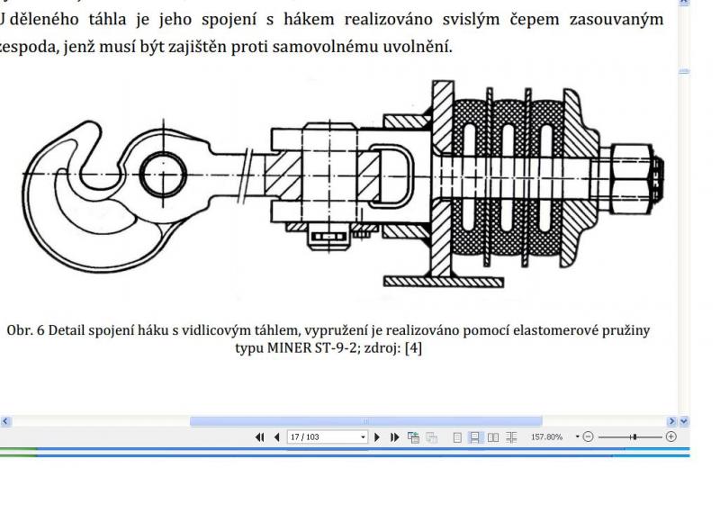
Not quite, the 'chain', is sprung between a pivot just behind the hook on the carriage, and the hook on the locomotive.
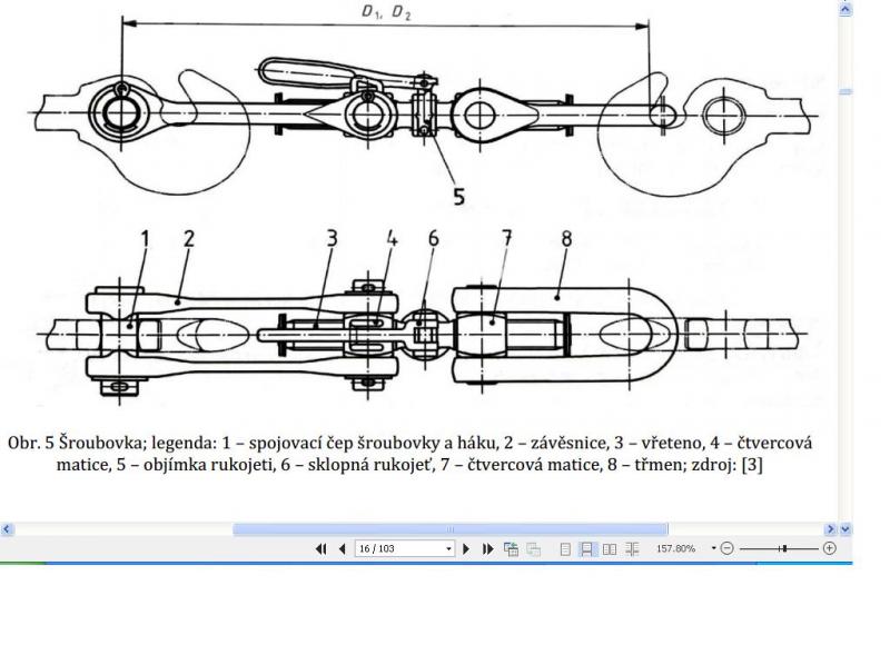
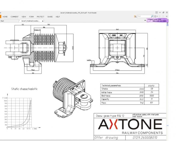
A screw/spring coupler typically exists from a hook, a shackle that pivots just behind the hook, and connects to a thread, on which a second shackle mounts that can be connected to the hook of another vehicle. When the shackle is placed on the hook, the thread is used to tension the coupler until the buffers of both vehicles are slightly pressed (if I recall correctly), creating a (semi-)rigid connection between the vehicles.
The spring thus should never loose tension during operation, ensured by the buffers keeping as most distance between the vehicles as allowed by the coupler.
The use of this type of coupler is (at least here in the Netherlands) bound to a number of rules, of which most peculiar is that when an unmotorised vehicle, a carriage or a wagon, is coupled to a motorised vehicle (locomotive or multiple unit, in which the tender of a steam engine counts as part of the engine), always the spring of the unmotorised vehicle is used, except when it is damaged.
I think this poses four challenges to the programming to model correctly:
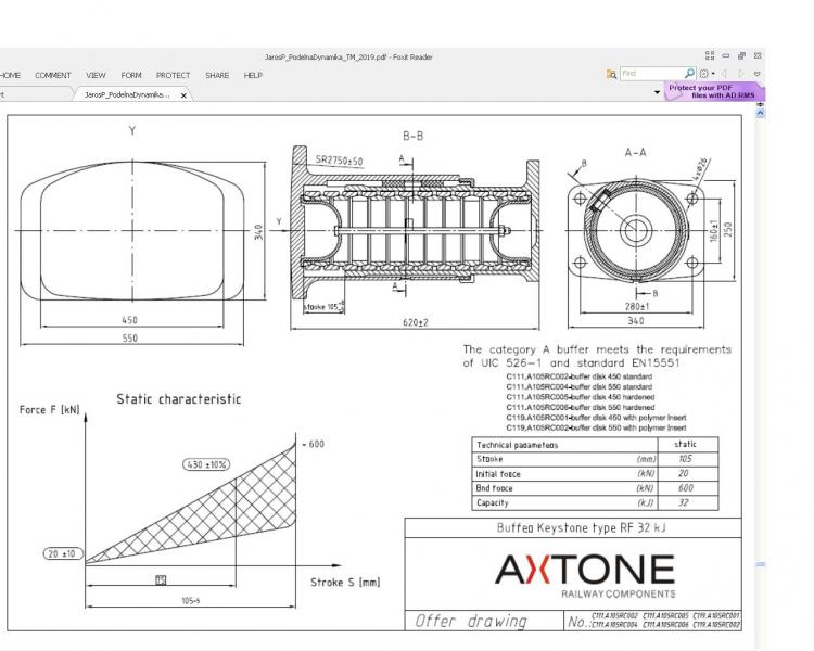
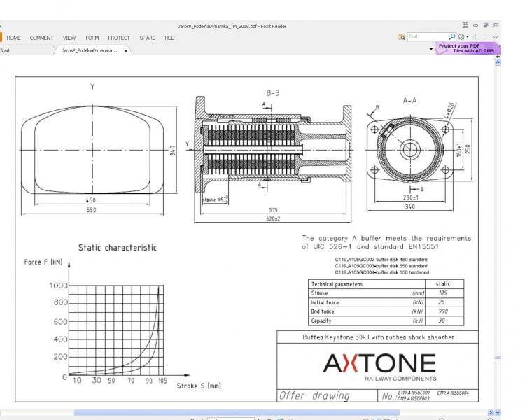
- Buffers: As mentioned, the buffers play an active part in tensioning the coupler. However, this is quite predictable, and for normal gauge the position is standardised on 875mm from the center of the vehicle (1750 mm apart), and between 1040 and 1060 mm from the ground[2]. This however varies when looking at different gauges.[1]
- Back-up-couplers: In the past, some countries enforced the presence of a back-up coupler underneath the main coupler that was not tensioned, so the train would not break when the main coupler broke. This practise was abandoned after the continued brake line became compulsory on all railway vehicles in the 1930s[3], but the presence of back-up couplers persisted until the end of the steam era in some countries, as some companies didn't bother to remove them.[1]
- Directionality: As mentioned before, there are some rules about which spring, and which hook is used. In many cases, but not by regulation, a consist of carriages or waggons is coupled in one direction, so if the spring of the carriage is used on one side, the hook is used on the other, except for the coupler to the motorised vehicle: then always the spring of the unmotorised vehicle is used, regardless of which way the other side of the vehicle is coupled.
- Brake hoses and other hoses: Although the couplers themselves are tensioned rigidly, the brake hoses, auxiliary air hoses and for example steam heating hoses were not. This might be the biggest challenge of all, as it would run down to flexible hoses, and that will be quite the challenge to implement in models.
All in all it will be quite the challenge to get this type of coupler working realistically in the simulator, but I think most of us would be already quite pleased if a way is found around point 3, point 1 would be very nice and 4 spectacular. Point 2 would only be of interest to the rather small number of people in continental Europe that have studied steam era thoroughly, unless this was also in use in the UK, as the community of steam connaisseurs over there is a lot larger than on this side of the pond.
If it is of interest, I have got some drawings at my disposal in which the working of a spring/screw coupler is shown more detailed, as well as a drawing of a steam heating hose, but I cannot share them publically unfortunately.
[1]: I think that flexibility in the coupler itself can be solved mostly by having the shackles and thread as separate sub-objects to the coupler with correct pivots, this however leaves the question of tensioning, especially as not all buffers have the same length.
At rest most buffers were 610 mm in the Netherlands, but 650 was quite standard in Germany, and I have seen buffers of 597 mm on older drawings of Dutch steam engines.
This can be solved too, but that would require advanced logic in the shackles sliding up and down the thread.
[2]: The bandwith is a design bandwith, in practise the difference can be larger due to wear and tear to the wheels, and the load of the vehicle. My friends in the railway world tell me that regulations state that at all times two-thirds of the buffer area has to be in touch.
[3]: The last railway vehicles in the Netherlands were obliged to have a continued brake line in 1934, but I'm not sure if this was a UIC regulation, or if the Netherlands were downright late to the party, as quite often in railway history
 Log In
 Register Now!
 Help
Help