Elvas Tower: ORTSMaxTractiveForceCurves - Elvas Tower

Jump to content

  • 2 Pages +
  • 1
  • 2
  • You cannot start a new topic
  • You cannot reply to this topic

ORTSMaxTractiveForceCurves Reduce "power to the rail" when used Rate Topic: -----

#1 User is offline   R H Steele 

  • Executive Vice President
  • PipPipPipPipPipPipPipPipPip
  • Group: ET Admin
  • Posts: 3,433
  • Joined: 14-March 13
  • Gender:Male
  • Location:known universe
  • Simulator:Open Rails
  • Country:

Posted 04 August 2018 - 04:12 PM

Advanced Adhesion use of the ORTSMaxTractiveForceCurves block reduces power to the rails at Notch8 to approx. 50% +/-

1. Default MSTS eng file produces power to the rail - Notch8 - in the normal 90% range and is proportionally correct at all other power notches.

2. Default MSTS eng file with ORTSDieselEngines block ( via OpenRails folder/eng include file/Common.inc folder ) also produces normal power to the rails at Run 8 and proportionally correct at all other notches.

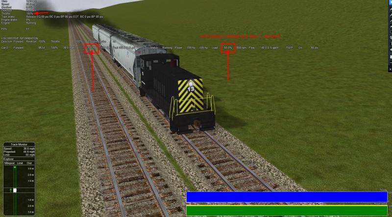
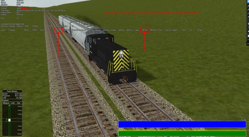
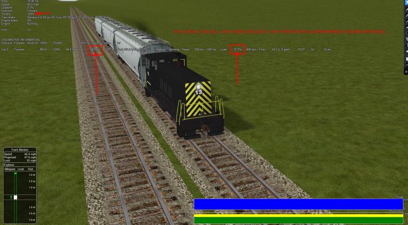
3. Adding the ORTSMaxTractiveForceCurves in any file configuration results in reduced power to the rails at Notch8, in the range of 50% (observed as low as 42% and as high as 70%), also proportionally lower at all other notches.**

4. All diesel locomotives tested, all routes, no log warning or error is observed.

5. Tests in the screenshot were with the locomotive and curve given in the manual on page 118, Sec. 8.1.4.1 ( see files used inserted in post )

**Note: file configurations --- MSTS default eng file with ORTSMTFcurves added to it ( No OpenRails folder); ORTSMTFcurves added to ORTSDieselEng block ( as shown Below) + MSTS default eng file; and ORTSMTFcurves only ( OpenRails folder/Common.inc) + MSTS default eng file.
Re-reading what I posted (and postings in another thread), I don't believe one can conclusively state that the fault lies with the ORTSMTF curves, it could very well be a problem with the Advanced Adhesion model. I'm thinking how to test that? Anyone know the advanced adhesion code?...that's not something I could tackle.


Comment ( Standard ORTS Diesel Engine for GE_70Ton Locomotive )
Comment ( Performance Ratings == Gross HP 700  == Traction HP 600 == 23605lb CTE == 41590lb MTE )
Comment ( include ( "..\\..\\Common.inc\\Locomotives\\GE_70Ton.inc" ) )

ORTSDieselEngines ( 1
  Diesel(
   IdleRPM ( 315 )
   MaxRPM ( 800 )
   StartingRPM ( 275 )
   StartingConfirmRPM ( 350 )
   ChangeUpRPMpS ( 65 )
   ChangeDownRPMpS ( 35 )
   RateOfChangeUpRPMpSS ( 25 )
   RateOfChangeDownRPMpSS ( 15 )
   MaximalPower ( 521.990kW )
   IdleExhaust ( 1.2 )
   MaxExhaust ( 2.3 )
   ExhaustDynamics ( 2.2 )
   ExhaustDynamicsDown ( 0.8 )
   ExhaustColor ( 20161819 )
   ExhaustTransientColor ( 40212324 )
   DieselPowerTab (
  	0   0
    350   55928
    415   111855
    480   167783
    545   223710
    610   279638
    675   335565
    740   391493
    800   447420
   )
   DieselConsumptionTab (
    0	0
    315  37.9
    800  151.4
   )
   ThrottleRPMTab (
    0   315
    12.5  350
    25  415
    37.5  480
    50  545
    62.5  610
    75  675
    87.5  740
    100  800
   )
   DieselTorqueTab (
    0 	0
    315  2951
    800  23605
   )
   MinOilPressure ( 20 )
   MaxOilPressure ( 50 )
   MaxTemperature ( 120 )
   Cooling ( 3 )
   TempTimeConstant ( 720 )
   OptTemperature ( 71 )
   IdleTemperature ( 55 )
  )
 )
 ORTS (
 ORTSEmergencyCausesThrottleDown ( 1 )
 ORTSWheelSlipCausesThrottleDown ( 1 )
 ORTSMainResChargingRate ( 0.237 )
 ORTSBrakePipeChargingRate ( 40 )
 TrainPipeLeakRate ( 0.0833 )
 ORTSEngineBrakeReleaseRate ( 38 )
 ORTSEngineBrakeApplicationRate ( 34 )
 ORTSBrakePipeTimeFactor ( 0.003 )
 ORTSBrakeEmergencyTimeFactor ( 0.1 )
 ORTSBrakeServiceTimeFactor ( 1.009 )
 )
 ORTSMaxTractiveForceCurves ( 0 ( 0 0 50 0 )
   .125 (
    0 23125
    0.3 23125
    1 6984
    2 3492
    5 1397
    10 698
    20 349
    50 140 )
   .25 (
    0 46250
    0.61 46250
    1 27940
    2 13969
    5 5588
    10 2794
    20 1397
    50 559 )
   .375 (
    0 69375
    0.91 69375
    2 31430
    5 12572
    10 6287
    20 3143
    50 1257 )
   .5 (
    0 92500
    1.21 92500
    5 22350
    10 11175
    20 5588
    50 2235 )
   .625 (
    0 115625
    1.51 115625
    5 34922
    10 17461
    20 8730
    50 3492 )
   .75 (
    0 138750
    1.82 138750
    5 50288
    10 25144
    20 12572
    50 5029 )
   .875 (
    0 161875
    2.12 161875
    5 68447
    10 34223
    20 17112
    50 6845 )
   1 (
    0 185000
    2.42 185000
    5 89400
    10 44700
    20 22350
    50 8940 )
  )


include ( "..\\bc13ge70tonner.eng" )
Wagon (
 include ( "..\\..\\Common.inc\\Locomotives\\Std_TypeF_Coupler.inc" )
 include ( "..\\..\\Common.inc\\Locomotives\\Std_Loco_Brakes.inc" )
 ORTSAdhesion ( ORTSCurtius_Kniffler ( 7.5 44 0.161 0.7 ) )
 ORTSAdhesion ( ORTSSlipWarningThreshold ( 70 ) )
 ORTSBearingType ( Roller )
 ORTSDavis_A ( 920.72 )
 ORTSDavis_B ( 20.8947 )
 ORTSDavis_C ( 5.485595 )
 Comment ( == Assumptions -Locomotive diesel/electric - speed - 55mph (89km/h), Roller Bearing, 4 axles, frontal area - 10.6m2, WagonWeight - 63.5 ton (metric), Drag 0.90 == )
)
Engine (
 Effects (
  DieselSpecialEffects (
   Exhaust1 (
   -0.405 4.3 -0.417
   0 1 0
   0.13
   )
  )
 )
 include ( "..\\..\\Common.inc\\Locomotives\\GE_70Ton_TEST.inc" )
)

Attached thumbnail(s)

  • Attached Image: MSTS- NO ORTS.jpg
  • Attached Image: ORTS+MSTS.jpg
  • Attached Image: ORTS+MSTS+MaxTractiveCurves.jpg


#2 User is offline   Hamza97 

  • Engineer
  • Group: Status: Contributing Member
  • Posts: 606
  • Joined: 01-March 15
  • Gender:Male
  • Simulator:Open Rails
  • Country:

Posted 04 August 2018 - 07:40 PM

Yes I agree with what Gerry is saying..., I have observed same phenomena... :wtf01: :wtf01:

#3 User is offline   copperpen 

  • Executive Vice President
  • Group: Status: Elite Member
  • Posts: 3,143
  • Joined: 08-August 05
  • Gender:Male
  • Simulator:MSTS & OR
  • Country:

Posted 05 August 2018 - 11:47 AM

The fact that an unaltered MSTS eng file gives proper TE readings suggests that it is not the advanced adhesion at fault, but the overly complicated method of using multiple TE curves, one for each throttle setting.

The steam locomotive code as far as I am aware, generates the TE in real time using data from the eng file, current control settings, speed and steam pressure.

That is the same method used by OR for diesel locomotives, and probably electric as well, when the suspect TE curves are not in use, eng file data, control settings and speed.

#4 User is offline   R H Steele 

  • Executive Vice President
  • PipPipPipPipPipPipPipPipPip
  • Group: ET Admin
  • Posts: 3,433
  • Joined: 14-March 13
  • Gender:Male
  • Location:known universe
  • Simulator:Open Rails
  • Country:

Posted 07 August 2018 - 11:46 AM

View Postcopperpen, on 05 August 2018 - 11:47 AM, said:

The fact that an unaltered MSTS eng file gives proper TE readings suggests that it is not the advanced adhesion at fault, but the overly complicated method of using multiple TE curves, one for each throttle setting.

The steam locomotive code as far as I am aware, generates the TE in real time using data from the eng file, current control settings, speed and steam pressure.

That is the same method used by OR for diesel locomotives, and probably electric as well, when the suspect TE curves are not in use, eng file data, control settings and speed.


I agree. I have a few suggestions,

Why not adopt the method the steam locomotive code uses to generate TE to the diesel code. IMO, it would be preferable to having users make up the curves, when the proper code could do it real time.

With the introduction of new ORTS parameters that would provide the inputs, for instance
ORTSDieselLocoMass; ORTSCTE -- for continuous tractive effort; ORTSMTE -- max tractive effort and wouldn't there need to be an input for number of axles?
Whatever the parameters would be, they all could be added to the ORTSDieselEngines block. I'd much prefer that for Advanced Adhesion OR would generate the tractive effort curves. In any case, the Advanced Adhesion may need more work, as there are indications that I've seen ( and others have expressed to me in emails ) that it is not functioning as expected.

However, using simple adhesion produces almost no wheelslip in adverse weather condition on a grade of 2%, it is too easy...not realistic by any measure.
So, there is a real need for a properly functioning Advanced Adhesion code.
My preference would be that it is the default mode of operation, the user could always choose the simple adhesion if preferred.

#5 User is offline   sim-al2 

  • Hostler
  • Group: Status: Active Member
  • Posts: 76
  • Joined: 23-February 12
  • Gender:Male
  • Simulator:Open Rails
  • Country:

Posted 09 August 2018 - 03:57 PM

One issue though is that most diesel locomotives (and most electric locomotives and railcars) have non-linear throttle behavior, particularly at low throttle positions. MSTS didn't have a decent way to handle this and just assumed linear behavior, which is not particularly accurate. Behavior varies by locomotive type so procedural curve generation could be rather complex to implement. This is why I think the OR TE curve(s) addition is rather useful, though I agree that it could be easier to use (in particular, the current format is a bit clunky for the use of spreadsheet caculations).

For reference I've attached a SD40-2 TE curve from a 1980s Department of Energy/NASA study titled "Future Fuels and Engines for Railroad Locomotives".

Attached thumbnail(s)

  • Attached Image: SD40-2_TEcurve.jpg


#6 User is offline   Jean-Paul 

  • Fireman
  • Group: Status: First Class
  • Posts: 178
  • Joined: 28-October 14
  • Gender:Male
  • Simulator:Open Rails
  • Country:

Posted 11 August 2018 - 06:34 AM

Hello !
Just one remark on the subject above. I use Effort curves systematically on every type of engines (except "gear-boxed" railcars in which use is not possible). I noticed that ORTS doesn't support easily that speed references are different from one notch to another (see file above, where "speedmarks" are not the same from one notch to another). Probably because effort values are extrapolated when speed varies. It induces quick variations in effort, and it could vary from 10 to 100 % in half a second ! Calculation process seems to be too long to allow a pseudo-constant progression, or program hesitates between lowest and highest value - I don't know ! (Look at Shift+F5/Shift+F5/Shift+F5/Shift+F5, when number of substeps is displayed... Number is very high in this case- more than 100 - and indicates a complex calculation. It depends also of acceleration : when speeds varies quickly, quicker calculations are required ! ).
Having practiced with very complicated curves (DC electric engines with graduator, or AC with direct motors), I recommand that choosen speeds would be systematically the same for every notch, even if a particular value is not useful for considered notch. For instance, at notch 0, I indicate a null effort for every value mentioned in the notches. In these conditions, I've never had a problem, even with complex curves (for instance, two or more inflexions with increasing speed). With french old DC engines, I have up to 64 notches, which give you much, much work to write, but it works absolutely perfectly. I even noticed an increased fps by comparing with MSTS classical configuration.
In fact, OR is more "comfortable" with regular and linear variations, probably because extrapolation is much more easier in this case.
In my opinion, it would be a mistake to align electric/diesel curves on steam curves calculation : calculation logics have nothing common...
Hoping this reply could be useful ! :rolleyes:
Cheers,
Jean-Paul

#7 User is offline   Jean-Paul 

  • Fireman
  • Group: Status: First Class
  • Posts: 178
  • Joined: 28-October 14
  • Gender:Male
  • Simulator:Open Rails
  • Country:

Posted 11 August 2018 - 07:13 AM

(Re)-hello !
Perhaps it could help if I explained how I process, without any pretention.
If I consider EMD SD40-2 curves above, I notice :
- A first inflexion around 7.5 mph (3.3 m/s) for notches 5 to 8
- An inflexion around 3 mph (1.3 m/s) for notch 7
- A "break" (probably due to shunting motors ?) around 17-18 mph (7.8 m/s) for notches 3-4-8
1°) So I decide to retain following speeds for every notch : 0 - 1.3 - 3.3 - 5 - 7.8 - 7.9 - 10 - 15 - 20 -25 - 30 (unit is m/s). Bold values are those suggested by real effort curves.
2°) I open MS Excel, and I make a table reporting, for every notch, couples (speed/effort)
3°) Processing for every part of the curves, I determinate a convenient statistic equation which allows me to predict values for every speed considered. Sometimes, it's linear (first part of curves, for instance), and logically of a v^x where x is negative for decreasing part of curves. Excel do this very easily !
4°) A "break" like, here, between 7.8 and 7.9 m/s is easy to replicate : previous part of the curve stops @ 7.8, following begins @ 7.9. OR accommodates perfectly of this (even if it will never be a "sudden" break, because of extrapolation). Here, only three notches are "breaking" (3-4-8). No problem for others which are continuous : they don't change of equation, but I'll have to report effort value for 7.8 and 7.9, that's all !
5°) I print my Excel sheet and report values under the same form for every notch :
Notch Value (for instance 0.25) (
0 0
1.3 aaaaa
3.3 bbbbb
5 ccccc
7.8 ddddd
7.9 eeeee
10 fffff
15 ggggg
20 hhhhh
25 iiiii
30 jjjjj )
Here, with only eight notches, it will not be too long ! :rolleyes:
I must precise that in phase of strong acceleration, some "hesitations" are possible, though, but they are not too long. And also that transmitted power at rail is systematically lower than indicated in the curves, because OR takes in account wheelslip (and that's a realistic quality !!!).
I hope this will help more !
Cheers !
Jean-Paul

#8 User is offline   R H Steele 

  • Executive Vice President
  • PipPipPipPipPipPipPipPipPip
  • Group: ET Admin
  • Posts: 3,433
  • Joined: 14-March 13
  • Gender:Male
  • Location:known universe
  • Simulator:Open Rails
  • Country:

Posted 11 August 2018 - 09:26 AM

Thank you Jean-Paul, great information...I believe I understand what you are doing, going to rework my curves and test again.
http://www.elvastower.com/forums/public/style_emoticons/default/sign_thank_you.gifhttp://www.elvastower.com/forums/public/style_emoticons/default/hi.gif

#9 User is offline   R H Steele 

  • Executive Vice President
  • PipPipPipPipPipPipPipPipPip
  • Group: ET Admin
  • Posts: 3,433
  • Joined: 14-March 13
  • Gender:Male
  • Location:known universe
  • Simulator:Open Rails
  • Country:

Posted 11 August 2018 - 06:12 PM

View PostJean-Paul, on 11 August 2018 - 06:34 AM, said:

... For instance, at notch 0, I indicate a null effort for every value mentioned in the notches. ...
Jean-Paul

OR does not have a warning in the log about interpolator needing increasing values?
In this instance could you provide example of how ORTSMaxTractive Curve block is constructed?

#10 User is offline   Jean-Paul 

  • Fireman
  • Group: Status: First Class
  • Posts: 178
  • Joined: 28-October 14
  • Gender:Male
  • Simulator:Open Rails
  • Country:

Posted 12 August 2018 - 01:06 AM

View PostR H Steele, on 11 August 2018 - 06:12 PM, said:

OR does not have a warning in the log about interpolator needing increasing values?
In this instance could you provide example of how ORTSMaxTractive Curve block is constructed?

Hello !
Yes, that's right, but here, at notch 0, effort is necessarly null for any value of speed, no ? (corresponds à 0.00 notch). So, effort is increasing when I pass to higher notch. Must mention I experimentate a config for a french AC/DC locomotive, in which max DC power is lower than AC power. Willing to preserve ability of engine to be a real dual voltage, able to change pantograph and current "on-line", I did a .eng where two notches @ 0.85 and 0.86 where effort is null, to mark a difference between AC/DC common notches and pure AC notches, higher than 0.86. It works without any problem, despite this annulation of effort. I join the file. Don't be afraid of very high values of effort at start or low speed ! I know they are not possible in practice, but I'm not wrong, considering that with an electric engine without electronics, you never start @ 100 % (at max @ 10-15 %). Theoretical effort of a DC motor with collector is aiming at infinite at null speed, in fact (not the same for three-phase motor). And it also allows to have very realistic wheelslips if you drive like a dummy !! You'll be probably astonished to see that some values are very similar (0.3750 to 0.3755, for instance). OR supports this very well, and it allows a perfect simulation of successive shunts at the end of a coupling of motors : efforts remain the same at low speeds, but weakening of electric field by increasing shunting level allows better efforts at high speed. Despite this apparent complexity, number of substeps with such an engine doesn't excess 10 in strong acceleration phase, but generally 1 (difficult to do better :derisive: !) in quasi-constant speed riding. Of course, driving is much more difficult than with usual MSTS config, but it's the game, no ? :victory:
I'm going to try to work on SD40-2, following values given and commented yesterday. In fact, I have already configured SD40-2, but I had not these informations.. So, I did following my idea, and only based on EMD documentation concerning effective Diesel speeds following notches. So, first part of my old file is probably right ! :dance3: Must also mention that I noticed that if everything is OK with two coupled engines, even four (for instance F7 ABBA), situation seems less favourable by using helpers at the end of trains : probably not because use of "include", but by adding more complex coupling effects acting on helper engines. It's more difficult again if an helper is flipped...
So, I let you discover !!
Cheers,
Jean-Paul

Attached File(s)


  • 2 Pages +
  • 1
  • 2
  • You cannot start a new topic
  • You cannot reply to this topic

1 User(s) are reading this topic
0 members, 1 guests, 0 anonymous users