Welding vertices generally refers to merging two vertices within a given threshold (say .001in) into a single vertex. Specifically, when I speak of welding UV coordinates, I am referring to ensuring that triangles which have vertices in the same place in UVW space have those vertices welded. The ability to do this is largely dependent on mapping layout. For example:
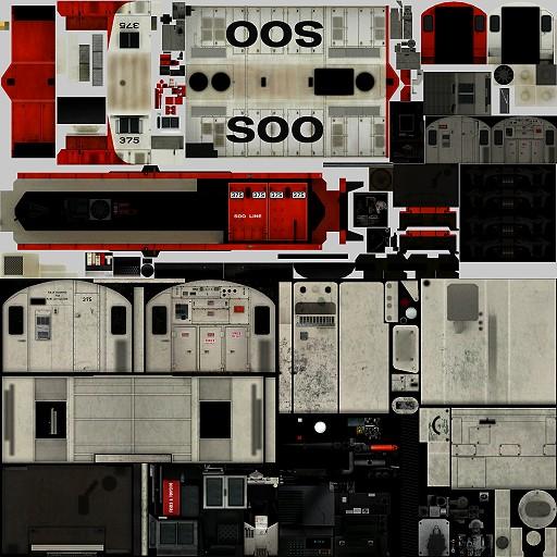
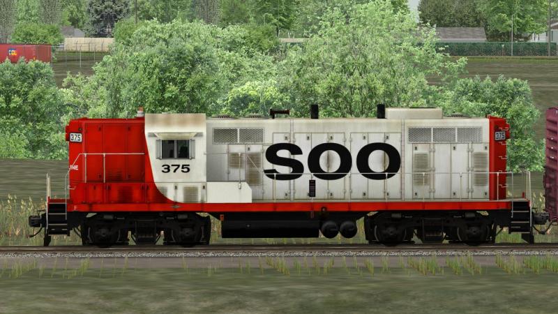
This is the diffuse map for one of my works-in-progress. I am going to concentrate on the long hood of this GP7.
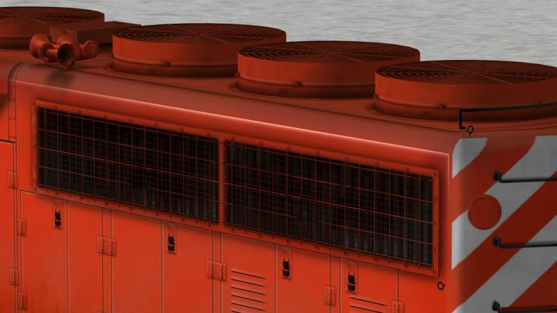
You can see that the sides and top of the long hood blend seamlessly into each other. This was deliberate (I don't texture by accident, I plan ahead very carefully, from a definite resolution - in this case 1/2 pixel per inch - to the optimum layout to minimize the number of maps and provide the greatest ease-of-use for repainters). I knew that, just as the top and sides, obviously, meet in the mesh, so too should their UV coordinates meet so that no coordinate was duplicated. This would not be possible on, say, an SD40-2, with its dynamic brake blister protruding out from the hood and creating the necessity of a gap between the top and sides, but I would ensure that the widest part of the hood - the dynamic brake blister - was a continuous surface from top to side, so that I could at least eliminate a few UV coordinates. In this case, the GP7 has a straight, uniform-height and width hood for me to work with, so that the UV coordinates end up looking like this:
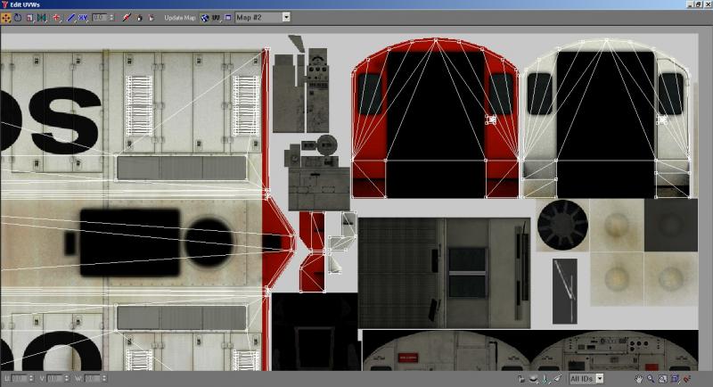
UV coordinates exist in a 3D space, so even though I had moved the coordinates so that they were coincident where possible in this plane, they would not weld. This is because they were still separated "vertically," that is, the UV coordinates were separated along a space perpendicular to the texture map. So I changed the coordinate display in Unwrap UVW from UV to UW - which shows us a "side" view of the coordinates - and scaled them vertically so that they were more or less along a straight line. This allowed colocated coordinates to be welded:
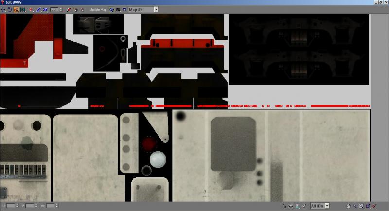
If we change our coordinate display to UV again, and again end up with this image, we can see some compromises that I made:
Note how the front and back of the cab are separated by some space. This is to avoid bleed-through from one "island" to the other due to antialiasing. If I didn't care about this, however, I could indeed select either the front or back, and move it left or right so that it shared an edge with the other "island," and weld the vertices accordingly.
Why does this matter? Because it's not the triangles that kill performance, it's the vertices that define them. Two models with identical triangle counts can differ wildly on vertex counts depending on mapping or smooth groups. When you create a hard edge, for example, the vertices at the edge may be welded insofar as the 3D program is concerned, but on export, they will be discrete vertices (this is how the hard edge is defined). So a cube that is smoothed over into one smooth group will have eight vertices, while a cube that has all hard edges will have 24. If you were then to map each face of the cube individually, with no continuity across any mapped surfaces, this vertex count would
double. If I were to take this hard-edge cube and map it so that all faces shared the same UV coordinates, then I would only be adding four, resulting in a total of 28. If I smoothed the cube over, it would become a 12-vertex deal.
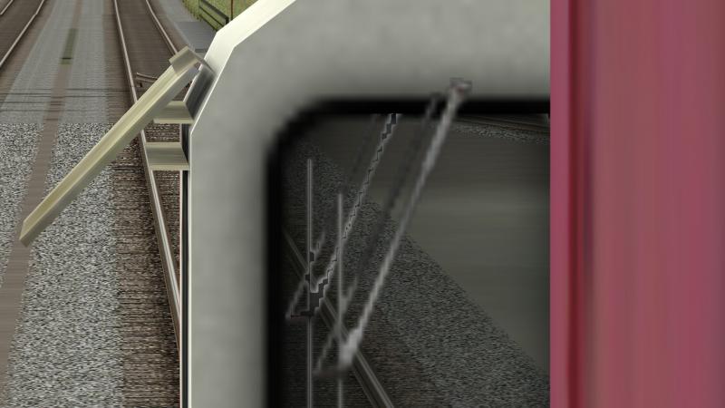
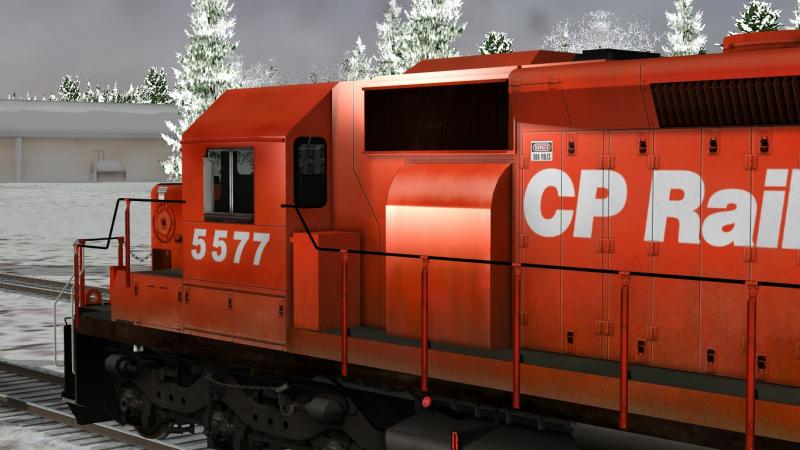
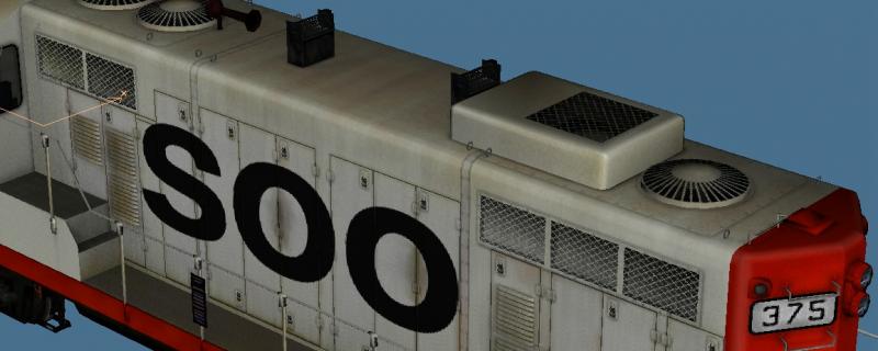
This is why I smooth over many minor parts, especially parts that will be dark and can have a hard edge simulated in the texture. You can see this on the stanchions and the radiator shutters.
The desire on my part to conserve UV coordinates is a prime driver in my tendency towards large, continuous surfaces, which, by necessity, leads to small numbers of large maps. This is also more efficient in terms of drawcalls, as the number of materials is a determinant of drawcall count. The ability of OR to handle all transparency requirements without a loss of bit depth is a critical component in drawcall reduction, as the entire model can now use a single material (whereas I would need to have a separate material for gradient alpha parts in MSTS due to its inability to handle gradient alpha without reducing RGB bit depth).
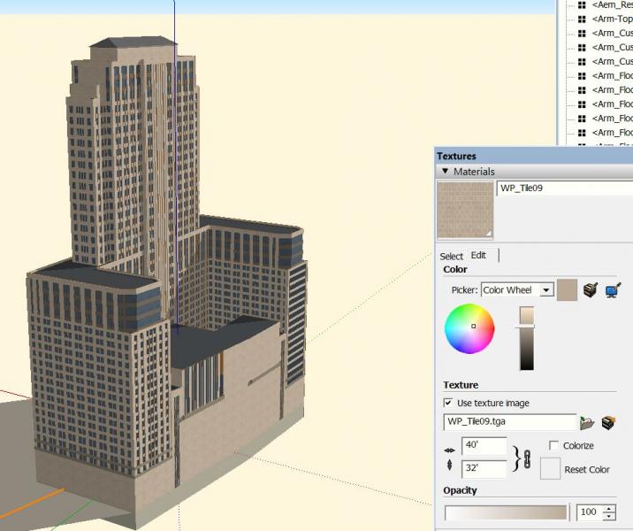
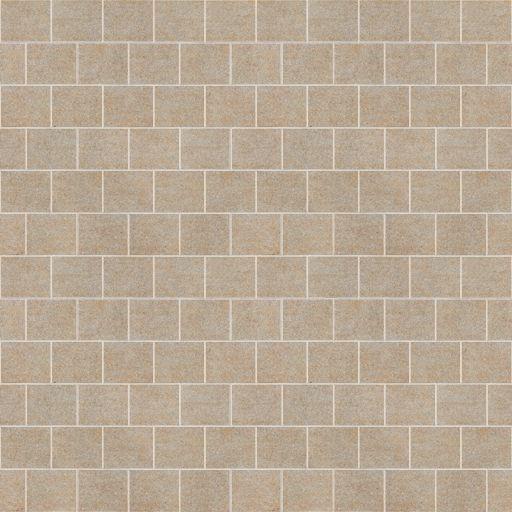
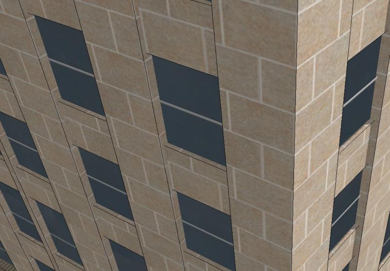
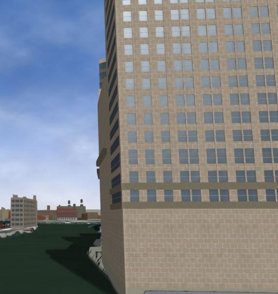
Dave mentioned in another post that he primarily works with buildings, which, depending on the target distance, can have their own specific issues with solutions that might not be compatible with this methodology. Specifically, large buildings meant to be viewed at close distances have the specific problem of a large surface area that needs a high amount of detail. The extra drawcall might be worth not having to manage a huge texture if a small texture that tiles can be used instead, especially since such a building would not likely be drawn more than once in an area. Smaller, generic buildings that won't be viewed up close and don't need the extra resolution would benefit greatly from being grouped into a single large map with relatively low resolution per building, with each building mapped as efficiently as possible. A move to non-cruciform trees is probably inevitable (because cruciform trees look awful outside of flight simulators), but trees that will always be hidden behind another row of trees ought to still be cruciform. This implies the need for careful planning and separate models for separate purposes - it's helpful to think of objects in terms of whether they are "hero" objects - viewed close up or in isolation - or whether they will be viewed distantly or will always be partially obscured (forests, for example). Model-building for MSTS and OR thus far has been somewhat haphazard. The visual demands of the contemporary PC game mean that a more coherent approach with high awareness of LOD levels, drawcall counts, object placement and visibility, and vertex counts, is desirable (to reinforce this fact, one of the major reasons for FSXs poor performance was the large store of poorly-optimized legacy content that ACES did not have the manpower to replace).
The "model railroad" system set in place by Kuju and continued in all modern rail simulators probably isn't helping, either. FSX uses about 9 GB of texture files to render the
entire world. True, that's about the same as a couple dozen routes, but consider how much ground that 9 GB covers. Also consider that the average route doesn't look much better or worse than FSX's autogen ground scenery, the number of routes is limited, and the number of route builders isn't exactly growing.
 Log In
 Register Now!
 Help
Help


 Genma Saotome, on 19 February 2018 - 06:15 PM, said: