 Log In
 Register Now!
 Help
Help

Basically wing it - else it is a trip to the museum where a couple might be available for detail photographs :)
Or either buy a OO model and copy what they have done, Bachmann will have some out soon, or a Colin Craig's example, or see if someone has a model you can either go look at or send photos :)
Modelling an FGA wagon
Struggling to find appropiete reference material.
Rate Topic:

#11

- Engineer
-

- Group: Status: Active Member
- Posts: 553
- Joined: 09-January 10
- Gender:Male
- Location:Bridgetown, Western Australia
- Simulator:Open Rails
-
Country:

Posted 07 December 2017 - 03:24 AM
#12
- Superintendant
-

- Group: Status: Elite Member
- Posts: 1,001
- Joined: 18-July 17
- Gender:Male
- Location:Hastings, MN, US
- Simulator:ORTS
-
Country:

Posted 07 December 2017 - 02:07 PM
I think that everything you need to know is in your references and this thread, to be honest. The only real question I have is whether or not the description given by FM ianmacmillan applies solely to the bar coupling end, the chain-and-buffer end, or both? Assuming that it applies to both:
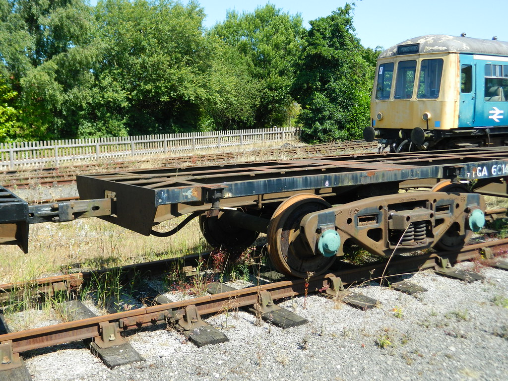
1.) The first piece of information is this photo. I presume, based on the raised portion and the presence of buffers, that this is the hook coupler end.
2.) A Bing image search on similar flats gives us this photo of the bar coupler end. Look very closely at where the bar enters the pocket. Above and below, you can see two dark shapes which look a whole lot like the two oblong shapes just outside where I presume the drawbar is in the first photo. We can conclude that the assembly seen in the first photograph is a pivot point and that the two oblong shapes on the side attach to the drawbar. This provides an axis of rotation, and I suspect that the assembly is attached to the car structure in a way that allows it to pivot the other direction.
3.) FM ianmacmillan tells us that "The bottom half is the same as the top but upside down. A square bar connects to an enclosed spring box under the cross member. The square bar forms the bar coupling at the other end." This tells us that the assembly works on the same basic principle as US-style draft gear. This German example of an automatic/buffer combination gives us an idea of what the pocket should look like.
4.) Do we see similar shapes in the flatcar? Yes, we do. Specifically, the area behind the face of the car, enclosed between the two frame rails. What about the location of the spring box? We see a region, in the vicinity of the first cross-member inboard of the face of the car, that is covered by a plate above (and we can probably assume below as well).
5.) Therefore, the assembly probably looks like this:
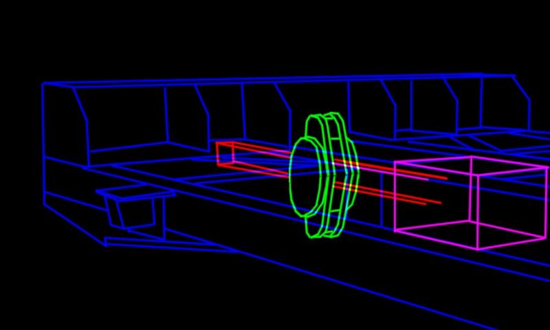
The car frame is outlined in blue, the drawbar mounting assembly in green, the drawbar in red, and the spring pocket in pink.
1.) The first piece of information is this photo. I presume, based on the raised portion and the presence of buffers, that this is the hook coupler end.
2.) A Bing image search on similar flats gives us this photo of the bar coupler end. Look very closely at where the bar enters the pocket. Above and below, you can see two dark shapes which look a whole lot like the two oblong shapes just outside where I presume the drawbar is in the first photo. We can conclude that the assembly seen in the first photograph is a pivot point and that the two oblong shapes on the side attach to the drawbar. This provides an axis of rotation, and I suspect that the assembly is attached to the car structure in a way that allows it to pivot the other direction.
3.) FM ianmacmillan tells us that "The bottom half is the same as the top but upside down. A square bar connects to an enclosed spring box under the cross member. The square bar forms the bar coupling at the other end." This tells us that the assembly works on the same basic principle as US-style draft gear. This German example of an automatic/buffer combination gives us an idea of what the pocket should look like.
4.) Do we see similar shapes in the flatcar? Yes, we do. Specifically, the area behind the face of the car, enclosed between the two frame rails. What about the location of the spring box? We see a region, in the vicinity of the first cross-member inboard of the face of the car, that is covered by a plate above (and we can probably assume below as well).
5.) Therefore, the assembly probably looks like this:
The car frame is outlined in blue, the drawbar mounting assembly in green, the drawbar in red, and the spring pocket in pink.
#13
- Fireman
-
- Group: Status: Active Member
- Posts: 197
- Joined: 23-October 13
- Simulator:OpenRails
-
Country:

Posted 07 December 2017 - 03:37 PM
 espee, on 07 December 2017 - 03:24 AM, said:
Basically wing it - else it is a trip to the museum where a couple might be available for detail photographs :)
Or either buy a OO model and copy what they have done, Bachmann will have some out soon, or a Colin Craig's example, or see if someone has a model you can either go look at or send photos :)
Or either buy a OO model and copy what they have done, Bachmann will have some out soon, or a Colin Craig's example, or see if someone has a model you can either go look at or send photos :)
ErickC, on 07 December 2017 - 02:07 PM, said:
I think that everything you need to know is in your references and this thread, to be honest. The only real question I have is whether or not the description given by FM ianmacmillan applies solely to the bar coupling end, the chain-and-buffer end, or both? Assuming that it applies to both:
1.) The first piece of information is this photo. I presume, based on the raised portion and the presence of buffers, that this is the hook coupler end.
2.) A Bing image search on similar flats gives us this photo of the bar coupler end. Look very closely at where the bar enters the pocket. Above and below, you can see two dark shapes which look a whole lot like the two oblong shapes just outside where I presume the drawbar is in the first photo. We can conclude that the assembly seen in the first photograph is a pivot point and that the two oblong shapes on the side attach to the drawbar. This provides an axis of rotation, and I suspect that the assembly is attached to the car structure in a way that allows it to pivot the other direction.
3.) FM ianmacmillan tells us that "The bottom half is the same as the top but upside down. A square bar connects to an enclosed spring box under the cross member. The square bar forms the bar coupling at the other end." This tells us that the assembly works on the same basic principle as US-style draft gear. This German example of an automatic/buffer combination gives us an idea of what the pocket should look like.
4.) Do we see similar shapes in the flatcar? Yes, we do. Specifically, the area behind the face of the car, enclosed between the two frame rails. What about the location of the spring box? We see a region, in the vicinity of the first cross-member inboard of the face of the car, that is covered by a plate above (and we can probably assume below as well).
5.) Therefore, the assembly probably looks like this:
 FFAflat.JPG
The car frame is outlined in blue, the drawbar mounting assembly in green, the drawbar in red, and the spring pocket in pink.
1.) The first piece of information is this photo. I presume, based on the raised portion and the presence of buffers, that this is the hook coupler end.
2.) A Bing image search on similar flats gives us this photo of the bar coupler end. Look very closely at where the bar enters the pocket. Above and below, you can see two dark shapes which look a whole lot like the two oblong shapes just outside where I presume the drawbar is in the first photo. We can conclude that the assembly seen in the first photograph is a pivot point and that the two oblong shapes on the side attach to the drawbar. This provides an axis of rotation, and I suspect that the assembly is attached to the car structure in a way that allows it to pivot the other direction.
3.) FM ianmacmillan tells us that "The bottom half is the same as the top but upside down. A square bar connects to an enclosed spring box under the cross member. The square bar forms the bar coupling at the other end." This tells us that the assembly works on the same basic principle as US-style draft gear. This German example of an automatic/buffer combination gives us an idea of what the pocket should look like.
4.) Do we see similar shapes in the flatcar? Yes, we do. Specifically, the area behind the face of the car, enclosed between the two frame rails. What about the location of the spring box? We see a region, in the vicinity of the first cross-member inboard of the face of the car, that is covered by a plate above (and we can probably assume below as well).
5.) Therefore, the assembly probably looks like this:
FFAflat.JPGThe car frame is outlined in blue, the drawbar mounting assembly in green, the drawbar in red, and the spring pocket in pink.
Although looking at the following images:
https://photos.smugmug.com/Wagons/F-TOPSCode/FFAFGA/i-3bTznLf/0/e9ec26aa/XL/FGA_601235_e_CreweBasfordHall_21072007-XL.jpg
https://photos.smugmug.com/UKRailRollingstock/F/FFA-FGA-Freightliner-flats/i-KT9brVL/0/965b0457/X4/FGA_601403_York_07062016%20%2859%29-X4.jpg
https://photos.smugmug.com/UKRailRollingstock/F/FFA-FGA-Freightliner-flats/i-db2vSBp/0/892ae65d/X4/FGA_601403_York_07062016%20%2863%29-X4.jpgThe drawhook appears to be higher than the frame and there's no evidence that the spring mechamism is above the frame as well.
This means that the spring may be on a different level which may mean that the black component is a type of lever rather then a linear component fitted onto the drawbar.
I wonder if that last image shows a little bit of the spring? Similar to this one.https://photos.smugmug.com/UKRailRollingstock/F/FFA-FGA-Freightliner-flats/i-8WzRzds/0/3e4d2abd/X4/FGA_601403_York_07062016%20%2864%29-X4.jpg
I think this might be the mechanism (it was a bit rushed so it's not to scale)
https://i.imgur.com/xgbNhfk.png
#14
- Chairman, Board of Directors
-

- Group: ET Admin
- Posts: 13,927
- Joined: 21-February 06
- Gender:Male
- Location:Way, way, way, South
- Simulator:MSTS & OR
-
Country:

Posted 07 December 2017 - 04:34 PM
Try not to model the spring in 3d, they a hugely greedy of polygons.
#15
- Superintendant
-
- Group: Status: Elite Member
- Posts: 1,001
- Joined: 18-July 17
- Gender:Male
- Location:Hastings, MN, US
- Simulator:ORTS
-
Country:
Posted 07 December 2017 - 04:35 PM
That actually looks perfectly reasonable. I didn't spend much time looking at that end, so I assumed that the couplers were at the same height and that the same basic mechanism was working on both sides. Given your additional information, it seems to add a layer of context to FM ianmacmillan's post: The spring assembly would be more or less the same, but on one side, the link to the bellcrank assembly would conntect to the spring, but on the other side, the spring would connect directly to the drawbar. The hook assembly then attaches to the top side of the bellcrank.
Either way, it seems like it shouldn't be a terribly difficult or complex mechanism to model once everything is known. Those assemblies are often the most frustrating, you know it'll only take a few triangles, you know it'll enhance the look of the model, you know it won't take long, but you just ain't sure how it fits.
Ordinarily, I greatly simplify coupler assemblies due to the relative lack of visibility, but these appear to have a lot of exposed parts, so it definitely makes sense to build it. Even when a container is loaded, you'll still be able to see the underframe when the car goes over a bridge - something lots of MSTS designers seem to forget (hence the plethora of models that look hollow when viewed from below).
For a part that small, a full 3D part would probably be overkill, yes. But it might depend on the resolution of the surrounding areas to a degree (although the resolution of the surrounding areas would have to be really, really high). A carefully-constructed cylinder-and-alpha assembly can look great if the model builder takes into consideration the optimal viewing distance and adjusts the texture resolution accordingly. A critical part of this is an 8-bit alpha channel to avoid rough edges - i.e. use anti-aliased edges to your advantage. Since OR handles 32-bit textures well, whereas MSTS did not, you don't even need to take a hit on drawcalls because you can use a single BlendATexDiff material for everything. In this case, I think that this will do nicely if the spring ends up being visible.
Either way, it seems like it shouldn't be a terribly difficult or complex mechanism to model once everything is known. Those assemblies are often the most frustrating, you know it'll only take a few triangles, you know it'll enhance the look of the model, you know it won't take long, but you just ain't sure how it fits.
Ordinarily, I greatly simplify coupler assemblies due to the relative lack of visibility, but these appear to have a lot of exposed parts, so it definitely makes sense to build it. Even when a container is loaded, you'll still be able to see the underframe when the car goes over a bridge - something lots of MSTS designers seem to forget (hence the plethora of models that look hollow when viewed from below).
captain_bazza, on 07 December 2017 - 04:34 PM, said:
Try not to model the spring in 3d, they a hugely greedy of polygons.
For a part that small, a full 3D part would probably be overkill, yes. But it might depend on the resolution of the surrounding areas to a degree (although the resolution of the surrounding areas would have to be really, really high). A carefully-constructed cylinder-and-alpha assembly can look great if the model builder takes into consideration the optimal viewing distance and adjusts the texture resolution accordingly. A critical part of this is an 8-bit alpha channel to avoid rough edges - i.e. use anti-aliased edges to your advantage. Since OR handles 32-bit textures well, whereas MSTS did not, you don't even need to take a hit on drawcalls because you can use a single BlendATexDiff material for everything. In this case, I think that this will do nicely if the spring ends up being visible.
#16
- Fireman
-
- Group: Status: Active Member
- Posts: 197
- Joined: 23-October 13
- Simulator:OpenRails
-
Country:
Posted 08 December 2017 - 02:52 AM
I don't think the actual spring is exposed to the elements given the fact that there's a lot of plating on the wagon itself, this isn't the exact type of wagon but I feel it's close to give you an idea of how much plating there can be on these types of wagons https://youtu.be/g0kDOgcrOVc?t=474
I imagine that the spring would be encased in a housing, similar to the SA3 / Janney coupling and welded onto the frame similar to what you see in the US.
Edit: Something like this https://youtu.be/jjnnpxVghOM?t=92
I imagine that the spring would be encased in a housing, similar to the SA3 / Janney coupling and welded onto the frame similar to what you see in the US.
Edit: Something like this https://youtu.be/jjnnpxVghOM?t=92